1989 to 1998 Suzuki sidekicks and Trackers, as seen in USA. (REDUX)
How to save money , is this page and get the correct sensor (I cover more here, on how it works, with live signals)
Each maker , now has an online catalog to see all sensors for all cars, just Google them.
Buying and getting the right Oxygen sensor can be very hard, (the front sensor, not the rear).
Suzuki made this harder by having so many designs used, in 10 year span 1wire, 2, 3, and 4 wire. (the 4wire is best and runs the longest with out using body grounds for the CELL) (EPA laws are true causes)
Suzuki also changed Oxy sensor harness signal colors like a Mad Hatter.. (bad to the bone, IMO ) (or adds a relay just for fun...)
This Zirconia oxy sensor (or O² is a tiny 600ºC battery, that changes voltage based on oxygen differentials. (a tiny , 0v to 1v output).
Index:
- My new unified table? Just one table here, should answer all wiring questions. (and identification rules, for Calif or Federal cars)
- How to Replace it?
(If buying Plug and Play sensors, the only issues are getting the right
sensor and who has the best price? , but you can run the Universal
sensor just fine, to save cash)
- O2 sensors can not be truly tested ,outside a lab , but can be discovered DEAD or slow see here>, sensors & common failures.
- All aftermarket SENSOR brand makers color codes are here:
-
how to buy the correct Bosch sensor
using my Bosch part number table!
- How to wire Bosch Universal sensor
, wire to the 3pin Relay power O² sensor cars.
- ASE study guides to Oxy sensor O².
- Tools for O²
- What not to do?
- The mad color changes, on the CELL + (plus) pin (A Suzuki nightmare)
- G16 cars (Vitara's) that have no 02 sensors at all.
The bad ,weak or wrong reading O² sensor can cause many bad symptoms. (front , upstream sensors here)
- We replace it on suspicion (over 100k miles on it?), because it can not really be tested for accuracy, only if it is dead, can we prove it's bad or you have exhuast leaks near it, making it seem bad and is NOT A BAD SENSOR.
- The scan tool is your best friend here, (lacking a
scope) you can in fact check the 02 output and plot the signals
and see if they are good or bad. The scan tool can even report engine
running to lean or rich, IS IT?
- You can also watch LTFT , to see if this scanned live parameters, if reading way wrong? or correct at minus 5% is a good LTFT. (-40 and +40% are not)
- Dead means , stuck high or stuck low.
- Poisoned, is a O² That
is bad, or was destroyed by additives. (or oil smoking engines, or
other odd reasons, like antifreeze damage after a blown head gasket)
Most folks, just suspect this device, as being bad . $30 is a good price, and to me like buying new spark plugs, a good investment that pays dividends in fuel savings day by day. (pay back you get)
You can buy the Universal sensor for less and the connect below is missing , so you use the old connector. Saving CASH.
It is a 100,000 mile TUNE UP service point, part.
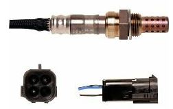
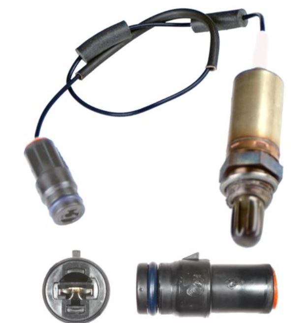
The below is a typical PNP (plug and play) O² sensor. A.k.a: the Narrow band sensor.
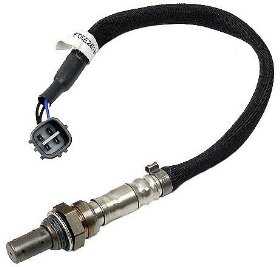 The Ubiquitous, O² Sensor, with heater and runs at 600ºC , Some can heat up in 6 seconds flat.
I will not cover the theory of how this sensor works. The internet has 1000s of pages on that now.
One good off site page for theory and some nice waveforms are at AA1.car
The rear O² sensor found on 1996 cars, and newer fails the P042x tests, means weak cat. (we replace the front sensor first, then drive and make sure the front sensor works, right, then if you can't clear the P042x codes
we replace the rear sensor, if that fails then the cat is replaced. (saving cash, not shot gun purchases!)
End rear, back to front sensors, only.
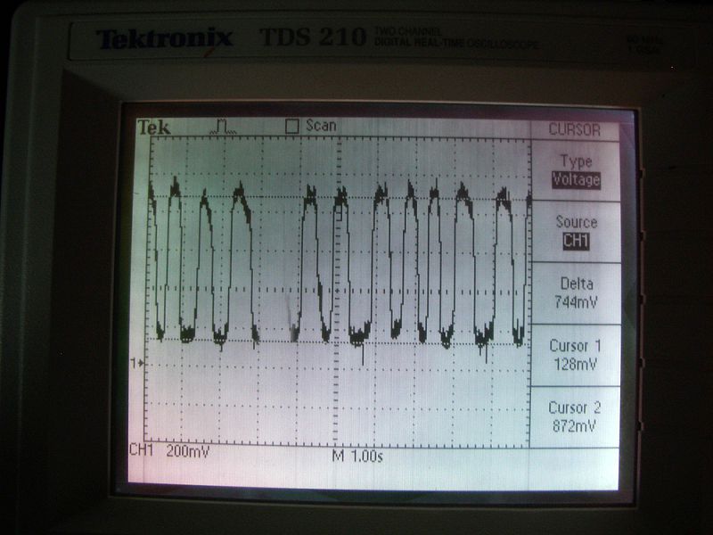
Lacking a scan tool are you:?
Have a SCOPE?
Any scope made can monitor any 02 sensors. and see its live swinging signals.
The front sensor governs the fuel injection rates, at idle, and cruising. (never accelerating or at wide open throttle or in cut fuel mode)
The sensor also proves engine passes smog tests. CEL lamp out running. That is the proof 1996 to today, (except the VW, bums)
Dead O² ? (stuck low or high)?
A dead O² is either a bad 02 or the ECU can not use the O², due to ECU locked up in Failsafe mode or there is an exhaust crack near this sensor, making it go dead.(not bad, just reads wrong)
One way to keep the 02 happy is to not run Car store sold , fuel additives (only do this is wild desperation) Why poison the O²?
References data, doc.'s and pages:
THE OFF CAR TEST OF THIS SENSOR . (you need voltmeter and a torch , real cave man methods... ONLY finds DEAD SENSORS..)
Another nice off site page, showing crosscounts rules.
See my typical OBD2 scans: See both analog and graphic plots.
See my V6 O2 sensor swap horror page.
Hand wiring a 1992 -1995 Sidekick/Tracker O2 sensor.
Ok, the sensors bad, now what?: REPLACE IT.
DO IT YOUR SELF (DIY):
One can save money by buying a Bosch(tm) brand sensors, that has just pig tail wires on the end. (sometimes).
You must get a color code cross reference for this method to work. ( Bosch has the pin out on their web site , here is 1991 8v pins.
The signal levels are very low and the connections must be perfect , in fact , I recommend using solder and special flux and heat shrink tubing.
The Bosch Universal sensors come with a splice kit, you can try that.
PARTS: Buy A cheap $5 Oxy removal tool and very useful
Is yours a 1,3 ,4 wire harness:
Do not trust your old shabby or wrong sensor is correct one, look at the harness wires, it plugs into..... this matters, (as does Suzuki spec.)
Below are some top makers catalogs, look yours up and see your choices.
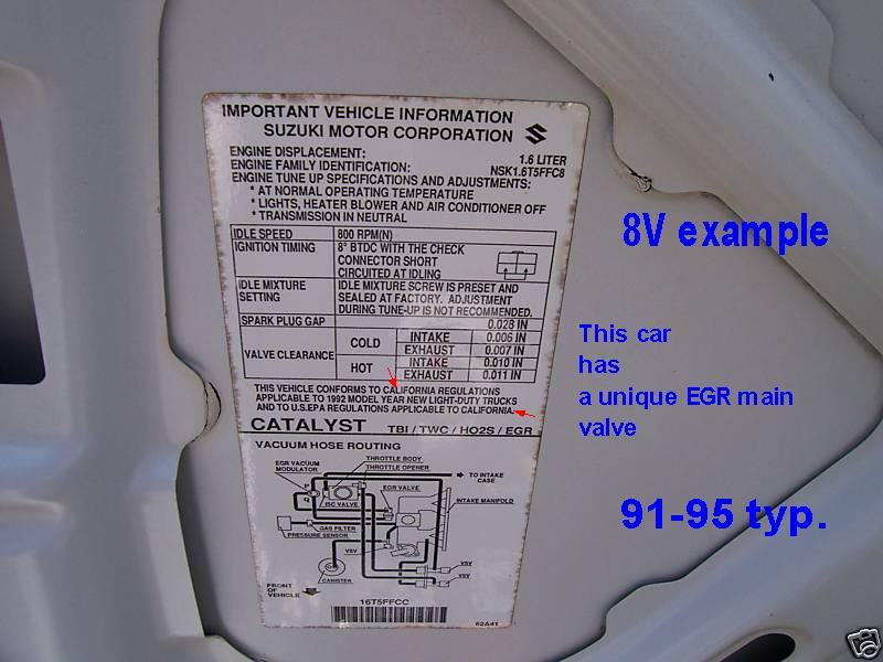
Codes used in stores, (due to missing Suzuki VIN engine code !) GM corrected this blunder... by adding real codes,. below.
KV = G16b = 16valves, =MPI = hard top, or VAN , GM VIN code 6, GM = GEO
KC= G16A = 8valves = TBI = soft top. or canvas top, GM VIN code "U"
Key facts to know , besides car engine type are:
- Connector color
- Connector pin count
- Connector wire count on car harness side.
- flat pins aor round.
- wire colors.
- See my new unified matrix for all these variances. in one simple chart.
Not a complete list of makers :
NGK (A.k.a. NTK !), catalog shows this for their O2 sensors.:
BOSCH E-CATALOG ( has many bugs) see my matric table below to see them all.
The Delphi E-Catalog. (electronic CAT)
DENSO Ecatalog.
nd others. Seen here (ex. 1995)
After finding the correct sensor, and matching to the Suzuki part numbers, and pin counts and the 5 item list just above, what I do is do a Google search on said part.
Like the common Bosch 15701
The biggest savings can be using the Universal fit sensor (hand wired) (I just did this on my V6)
The Suzuki p/n below is the suffix, the prefix for all is: 18213-
This table is not 100% accurate, in the fact that some 92-95 use different sensors .
What matters most, is wire harness wire count and connector color.
Federal cars usually uses the 3 wire and Calif 4. (but you need look first, look for connector color and wire count) Some aftermarket sensors have wrong connector color, using black for 4 pins.
The Bosch site is totally unclear on FED/CAL choices !
18213-
| Valve count |
Year 19nn |
Suzuki P/N Suffix |
Universal DIY
, Bosch P/N |
FED PNP Bosch P/N |
Calif PNP Bosch P/N |
Header Length & stud# |
GM RPO code |
Wire count |
| 8V | 89/90 |
61A10 | 11027-1 NO HEATER | 12050-1 | N/A |
n/a | both | 1 |
| 8V | 91-95 |
56B00 | 15726-3 |
15701-3 |
n/a | both | 3 | |
| 16v | 92/93 | 58B00 | 15730-4 | 15701-3 | 13073-4 | short 3 | NA5 | 3 |
| 16v | 93' C | 58B11 | 15730-4 | 15701-3 | 13073-4 | long 2 | NB2 | 3 fed 4 cal |
| 16v | 94/95 | 58B21 | 15726-3F 15730-4C |
15701-3 | 13073-4 | long 2 | both | 3 fed 4 cal |
| 16V | 96-98 | 58B21 | 15730-4 | 13073-4 | <same |
long 2 |
both |
4 |
| 16v | sport 1.8L |
77E00 | 15729-4 | 15287-4 | <same |
long 2 | both | 4 |
All the sensors listed above ,at Suzuki are discontinued at Suzuki, but the 77E00.
(one of the best deals around is the $21 , 3 wire sensor (there is (seems) always one on sale here)
Watch out , some items at ROCKauto.com fail to show or tell you its 3 or 4 wire, most times the black connector is 3 wire. (most folks can't figure out the CAL fed thing ,either, but here it is.... a photo of it...)
Gm (Geo parts)? yes they show 1 sensor , evern though in 1992 there are 3 sensors that year, 2 for MPI and 1 for TBI or can be 2 sensor, 3w and 4w but fails to show both nor which they are...
GM shows p/n 25161530 at $91 (shows same for 1991, so I know this number, for a fact is wrong for the G16B MPI California car (92-95) with 4 wires. Way to go GM ! (my guess you need to walk in and beg for correct answers.... A Geo what?)
End Suzuki sources end GM and BOSCH.
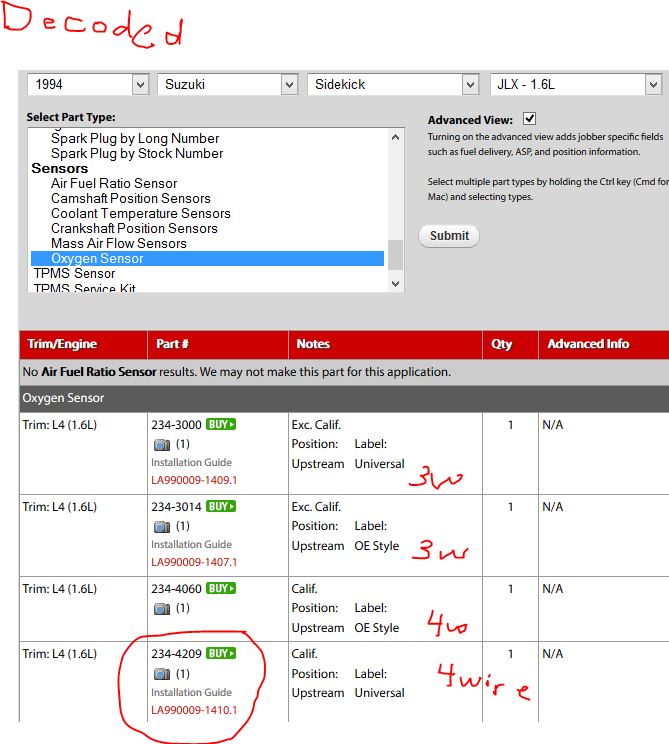
The Denso prefix 234-
-4209 calif 4wire 16valve engine
-3000 Federal. 16v
8valve is -3000
For the 3wire car, see below. (exc. Calif means except California, which means USA federal) why the sellers can't index by wire count, amazes me...after all some buyers are from CANada and need these facts)
The word OE style means PNP , plug in and play. (universal means no factory connector provided)
Photo1:
 See them
at rockauto ! A great place to see all sensors made for car!
See them
at rockauto ! A great place to see all sensors made for car!Aftermarket SENSOR wire colors are "not a standard", this is the cheat sheet to solve that riddle.
Suzuki calls this NCA, no color assigned. (due to the above pig tail rules)
Color maddness 101: (solved)! Do not read this or go slowly insane.... It's here for desperado's !
(factory side harness colors , not 02 makers pig tails) I think Suzuki broke the worlds record on "can't decide what colors to use and stick with it"!
CELL means, oxygen sensor output signal , which acts as a tiny 600 degree C , battery cell, The CELL + is output, & CELL -(minus) is quiet ground. (best)
If not sure, then read my schematics page for true colors. I can only do USA cars. (and some Canada)
The wires that changes colors at the drop of a hat (year/engine type/and Calif./Federal) is this wire (and others).
This is just the CELL+ or SIGnAL PIN below. CELL + is OXY output readings.
CELL + SIGNAL out: Watch out for red turning pink after 20 years. and some have a pink grouhnd wire that turns white after 20 years.
To avoid confusion , skin the harness wrap back to see TRUE colors and clean them use soap and water, clean it, then look. (had to read like 10 FSM books to learn this)
- Red/blue = (92-1995) 16 valve Federal-48
and 3wire sensors, (exc.
calif) (early short Exhaust manifold) This means RED
with a blue stripe.
- Yel/blue = 8v TBI motor with 3wire senor and all MPI 16v 4wire.(began with Calif vehicles 92-93) then in 1994/5, all motors MPI 16v. changed to this color.
- Red = 1989/90
- White = 1996 front , rear O2 Red/blu or Yellow
- Red/Blue 1997/98 front , rear 02 is Yel or Yel/Blu
- Red 1999 front Gray/Yel rear O2 1.6L and 2.0L
- 1.8L J18 SPORT 1996-98 J18 engines. DOHC engine. Pink/blk front , Pink/white rear.
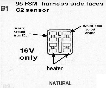
- 2.5L V6 H25 (pin 2) B1 = bank 1 is left B2 = Bank 2 right (2 upstream front sensors per below color rules (factory harness colors )
- H25 Front
B1S1 RED (left) Bank1 sensor 1
- H25 Front B2S1 Blu/Green (right)
2 common connectors used 1991 to 1998
1989/90 8v 91-95 8v--3wire 92-95 16v 4wire 1996 to 1998 4w.
In each case above 12vdc is Black-white power feed from fused KEYON.
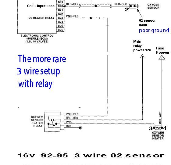
The rare 3 wire + relay setup as seen 1992 to 1995 See my unified wiring matrix here.
TYPE 3: (unlike schematic 3 above Type 2)
The relay is rare, I can not find the RELAY LOCATION no find places that sell them. I done not see Sensor makers selling the below sensors in the USA, so I suspect this below is for OUTSIDE USA markets.
In this case the ECU runs the relay and then energizes it to power the heater.
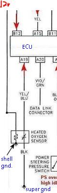
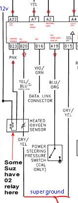
Look above at the 92 8v 3w, note how the sensor CELL- below is a shell grounded but above the ground is for the heater, so do not mix up 02 sensor, for 3wire.
Below CELL+ is red-blk.
The heater in this unique case is a floating (ungrounded) heater. I call this SGR ,for switched ground relay, setup.
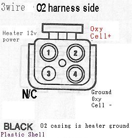
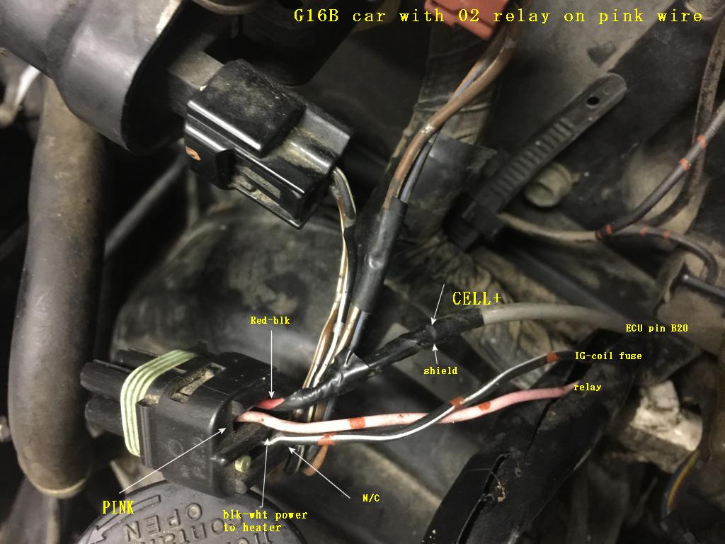
Example of a 3 wire sensor below, with the black harness covers skinned back? and shows the nice COAX cable used on most suzuki's for the CELL + pin. This is the RED-black VARIANT.
As you can see , ONE PIN is missing on this oxy sensor with a green plug. (ignore wire dots)
The pink wire is faded, from heat. I ?think? the below photo matches the above schematic, the relay 02 TYPE. (the relay most be good, and plugged in or the heater will be dead)
Photo.
See my unified wire matrix is here.
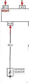
Photos: (real) 1991 TYPE1 , 3 wire. it just plugs in to a 4 pin (3 populate)d 02 suzuki connector on the right. There is no RELAY on this Oxy sensor this year.

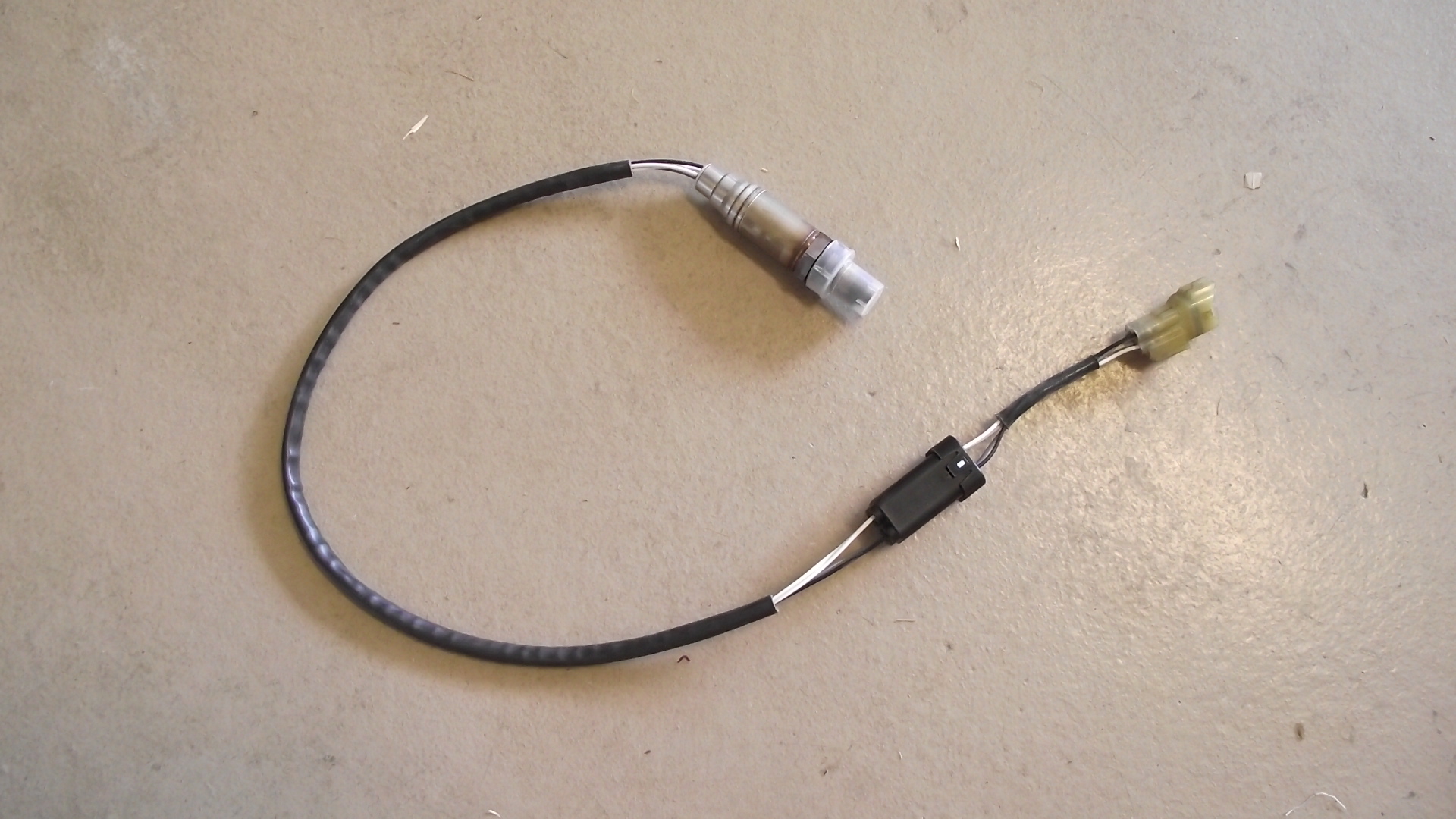
Seen below, is the 4 wire sensor , on the left is the Bosch ? universal adpator. the yellow connector on the right is the Suzuki standard 02 sensor connector 4 pins. that dangling wire is just the shield, should be taped of.
See my unified wire matrix here.
Type 5: below:
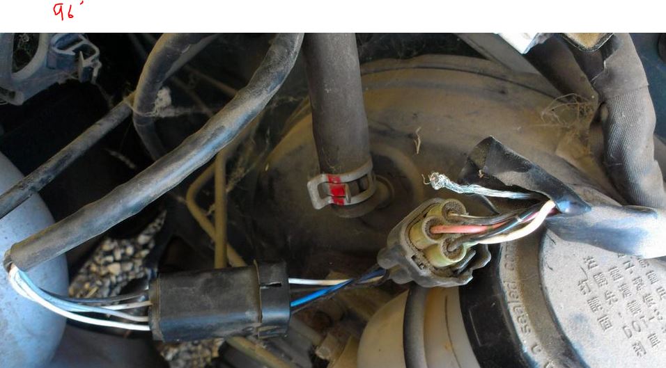
Above is 1996 to 1998, USA only. or why not buy the Walker sensor for $23 ?(PNP price)
That funny looking black cube above between 02 sensor and harness , is NOT STOCK, is the splice box, sold with universal sensors... (the do work great, but must be hand wired)
See my unified wire matrix here.
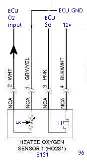
The below photo is of a 4 wire Oxy sensor plug. Note the flat pins and color. (yellow is called , natural ) (factory color, if car has aftermarket sensors the plastic can be any color)
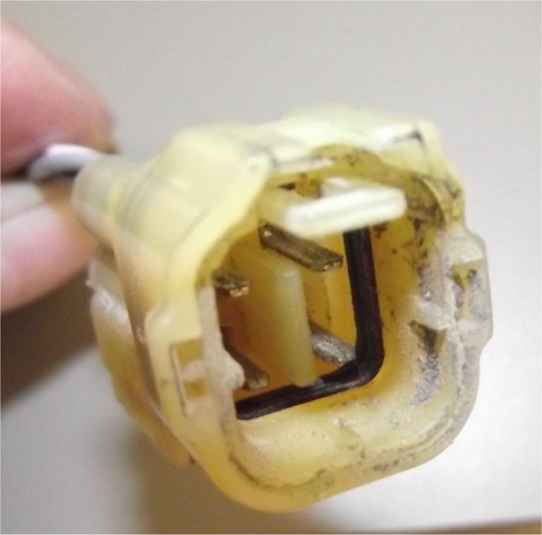
See my unified matrix wiring here.
One more three wire car harness. (type 2, no relay?)
You can see the pin missing clearly.
Note the round pins , unlike the 4 wire sensor, are flat.
If attempting to wire a 4 wire sensor to this 3 wire car, See my unified wire matrix , for the way.
In most cases the Black shell , means 3 wire.... (suzuki harness side) and the odd Female'ize male pins (transgender?) the missing pin is obvious. The missing pin means the 02 casing is the heater ground.
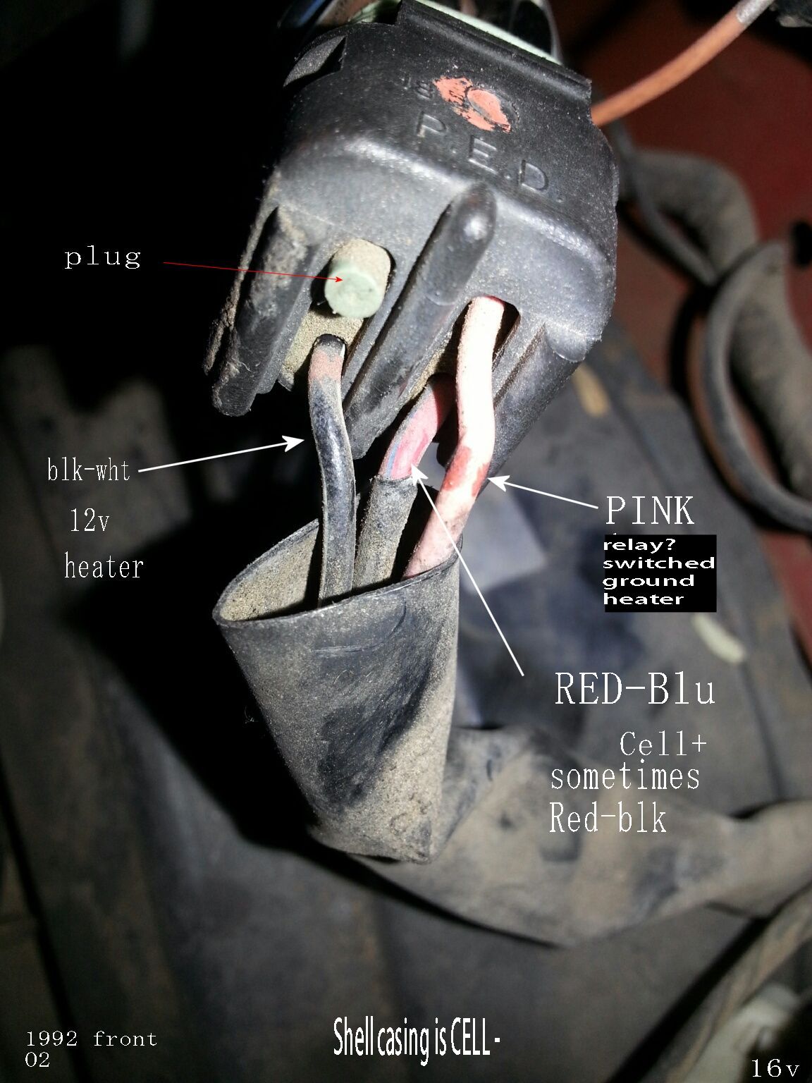
3 WIRE FRONT (harness end) Type 3 (variant) 1992 16v MPI
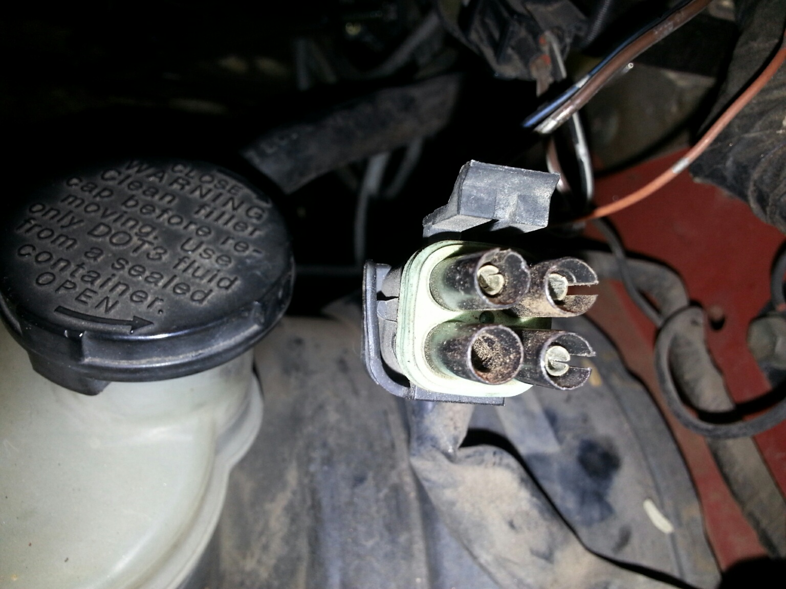
Rear View 02 front. Below:
That green thing, below, is water proofing plug on missing 4th pin.
Suzuki loves to use different colors here,
My guess as to colors and functions are in the photo.
I do not have good wiring diagrams for all 3wire 16v engines. (there are 2 types, CALIF and fed) I think the 4 wire is Calif cars, and 3 wire are FED. about 1994 and newer, all became 4 wire.
Type 3 (variant) 1992 16v MPI (I'm pretty sure about all markings below but the PINK wire, if pink at all, my guess now is it is NOT PINK, but RED-something)
The Below could be the RELAY version, Pink is heater switched ground, blk-white is 12v., red-blu (or red-black) is CELL + out (02 shell ground is CELL-)
The First ever Suzuki's Sidekicks, G16A uses the below:
The NO BRIANer one pin sensor , is a new BOSCH 1989/90 sensor, PNP. P/N 12050 It plugs into the RED harness wired connector. 1Pin. no heaters then.
Rockauto sells this for a whopping $11 bucks. DENSO is $17 !
Photo Type 0 (day 1 first cars)
My new G16 , Unified pin wire color table. (not 02 pig tail colors!) but actual Suzuki chassis harness wire colors: 1989 to 1998 (not J18 SPORT) s. Front , upstream sensors only.
Codes: 12 = hot 12v, SG = switched ground and G = grounded hard, 3W = Three wires SGR = Switched ground via, an O2 relay , under ECU control.
Color codes:
| Function |
1989/90 Type0 |
91+ Type 1 3W |
92+Type 2 3W |
Type 3 3W |
Type 4 4W | 96+ Type 5 4W |
Bosch colors(4w) |
comments |
| Heater 1 |
n/a |
BLK-WHT-12 |
BLK-WHT-12 |
BLK-WHT-12 |
BLK-WHT-12 | BLK-WHT -12 |
WHITE 12 |
The heater uses about 1amp of current. |
| Heater 2 |
n/a |
SHELL--G |
SHELL--G |
PINK--SGR |
PINK (SG) | PINK (SG) |
WHITE G |
Heater can be a fixed ground or switched, Some ECU even measure current here (1996+) |
| CELL + |
1 red wire |
YEL-BLU |
YEL-BLU |
RED-BLK |
YEL-BLU | WHITE |
BLACK (sig) |
Or RED/BLUE (this wire is the oxygen sensor output signal) Suzuki loved to change this color. |
| CELL - |
shell engine ground |
PINK - G |
BLACK |
SHELL--G |
GRAY-YEL | GRAY-YEL |
GRAY G |
GRAY-YEL is ECU super ground. (or quiet sensor ground) |
The CELL + Wire Can be, red-blu, yel-blu, red, white or even pink-blk (on J18 Sport engines)
I think this one table makes it easy to find , buy and install any new sensor.
Rule 1: The 4 wire harness is usually a yellow connector body but the 3 wire sensor is usually black connector body.
Rule 2: if wiring a 4 wire sensor to a 3 wire car, just connect both ground wires, to or SG or SGR, above. (by any means) The Universal 4 wire sensor can be made to work on both 3wire and 4wire cars, in this way.... next...
The Bosch 4w has 2 grounds, one is white, other is Gray , tie them together for 3 wire cars. then to Pink, or the Black Type 2 or 3 respectively, for 4 wire universal usage see table above.
Rule3; the 4wire sensor the heater is not polarized, nor grounded to the shell casing, this is called a floating heater. (do not fail to get all grounds working)
Rule4; do not buy PNP sensors with the wrong connector color, pin shape or pin counts
If using other sensors, for the above see the next link below, for all colors used...
My new table gets them all....For more odd colors see here .
All aftermarket SENSOR color codes are here:
The sensors design life is 100,000 miles or 80,000 on the dirty piggy 8v
Newer sensors are faster to cross count and do save fuel, compared older slow sensors.
Replace BANK1 sensor 1 , any time MPG drops. (front only) or B1S1 and B2S1 on a V6 .
Top cause of sensors under 100k miles failing are?, exhaust leaks near it, any leak the will cause it to lie. (no damage just lie like dog)
I can usually buy a Bosch sensor for about $30. (on sale) 2x that in most autostores. (and more)
Misc. facts: (you can weld on a new bung if you know this)
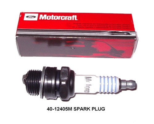
The 02 thread is 18mm 1.5 pitch , just like old 1960 Ford V8spark plugs and older cars used long ago, and makes finding chase tools or bung fittings easier when you know that.
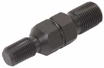
Photos and tools:
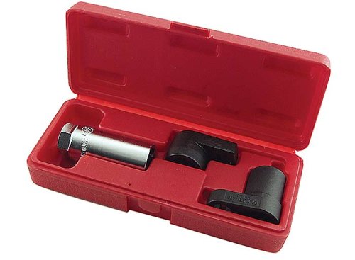
 My favorite tool; this.
The last tool above can be had for $5 at any Harbor Freight store in the USA.
The 1st photo shows a nice crow foot tool.
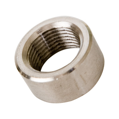
This is a weld on, bung fitting, if your's is mangled , then here is the fix , a 18mm 1.5mm pitch CALLED THE O² BUNG fitting , can be had dirt cheap. (watch out for scalpers.) The word bung is the fitting on a barrel of wine or beer. (or grog, mate)
What not to do?:
(endless really but I do a few)
- Do not hot wire electronics on your car. (for sure any ecu outputs) or boom you go, called letting the SMOKE OUT.
- Hot wiring means jamming 12vdc on to any node (any ECM/PCM/TCM/ABS or air bag modules , or any modules you have zero schematics and documentation )
- Do not use a OLD meters to measure OHMS on
the CELL - or CELL + pins, (some old meters have 22volt batteries inside) (most modern meters are ok) (volts readings are advised !)
- Do not put (jam) 12vdc on the ECU inputs. (attempting in vain to fool the ECU, just don't)
- If
you unplugged the O² the
ECU does pull this line up to 0.45vdc (a valid test), do not put
12vdc here, ever,but you can unplug it to hide the fact that the
exhaust leak here, causes the 02 to go very much nuts.
- The resistor heater can be tested 2 ways, any ohm meter
reads about 10 ohms across the heater pins with due care. or with
current meter, 1 amp flows key on.
- Do not make the mistake of crossing over the heater wire and CELL pins or risk blowing up a good 02 or ECU. ( some ECU's are protected from this act, but why risk a $400 ECU)
- Do not let the oxy sensor wires hit the hot exhuast ports, use tie back clamps....
- Do not clean any oxy sensor with solvents. (nor block there air breathing holes)
Last one I saw was in year 2000, some love their pure analog meters.
What can you do?, lots.
Do Use a modern SAFE DMM, on many new meters the max voltage on the OHMS scale is 0.7 vdc (RTM) or less. (&fails a diode test) but has a diode test mode (dial) that raises the voltage a tad and works on diodes and transistors. (RTM read the manual)
On Volts mode all is safe. (no meter internal battery feeds the test leads, in that mode)
Best of best, use a scan tool to plot 02 readings, or a scope or a graphing DMM, or a logging DMM that can scan over 10 times a second. (all these work , great)
A good sensor swings fast 5 to 10 times a second, at hot idle. if not?, its bad or there are exhaust leak near it or the ECU is stuck on failsafe mode. (best is a scope or scan tool to see these swings, about 6 times a second)
If engine runs rich, you cn unplug the 02 and see if RICH bets better (leaner) The ECU sets the 02 port to 0.45vdc . If the O2 is stuck at 0v, try finding and fixing exhaust leaks first. (near it) It must swing at hot idle or something is very WRONG.
Exceptions. (seems there always are... huh?)
The Slick Vitara's? Slick as in devoid of smog control parts.? (illegal in USA but folks have them world wide , and ask and I can answer)
JDM cars? (no 02 , no EGR, nor a CAT) > hit the home button, no oxy sensors here....
(JDM or Japan Domestic Manufacture, means to be sold only in JAPAN or to countries that allow owners to buy true JAPAN Market cars, like (Pacific Island sales are common , but never in the USA islands....)
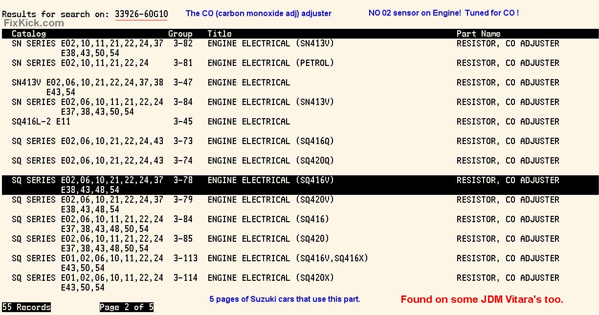
This engine is tuned, using a Carbon MonOxide meter. (CO meters) , Tuned to lowest point. (from high to low)
Some 1.6L Suzuki, sold in Japan (called a JDM) come with no O² sensors, , but has a Carbon Monoxide resistor device, for tuning, NON USA!
Some have no 02, no CAT and not EGR!
JDM means Japan domestic market
Suzuki P/N 33926-60G10 (the CO resistor) used on 100s of models sold world wide.
In the early days of EFI in USA, 1980s cars we used this same design, with CO tuning. (and a special meter, tail sniffer... ask and old mechanic. )
Over 10 Suzuki base class engines, used this Carbon Monoxide tuning device and have no O² sensor.
The 4 common market cars sold with no O² G16 engines, all.
SOME JDM cars and ..
06-- S. Africa RHD
11-- General export #2 ( sold world wide, but not USA) lots of these about.
21-- Belgium
43-- Saudi Arabia and more....
There are at least 18 other marketed Suzuki's that use this CO-Resistor. and ZERO OXYGEN SENSORs
All aftermarket SENSOR color codes are here:
rev.18-------------------- added 4wire to 3wire conversion drawing. 11-25-2012 (index, 10-4-2015) (losts of 3 wire updates) Redux, 12-21-2015, changed to a single unified table. for wiring. See my unified wire matrix here.