A.k.a: OXY sensor, O² (oxy atoms, love to bind up in pairs) and in Europe it's called by the Greek letter for Lambda this sensor, but some car makers call it and EGO (exhaust gas oxygen)
- In electrochemistry, lambda denotes the "equivalent conductance" of an electrolyte solution. The O² sensor CELL is really a high temperature battery (dead if cold) thus the refr. to electrolyte.
,
 say Lambda, 3 times and not laugh, or in mixed
company. I don't care what anyone calls it, we just want to test it.
say Lambda, 3 times and not laugh, or in mixed
company. I don't care what anyone calls it, we just want to test it. Facts:
You can not test the accuracy of any O² sensor (outside a full lab) . Only replacement, cures a biased sensor. The design life is 100,000 miles "Bosch states as does SUZUKI"
The sensor can be poisoned, biased and out of calibration, it can be shorted to ground (lean) or shorted to heater, (rich) and it can be dead, or weak, and the heater can be dead, open, or shorted to ground. (why not just replace it?)
This page covers front sensor, not rear. (rear have a special purpose that I will not cover here, but the off car tests are same.)
If the heater is dead, so will be the O² Cell part.
We can in fact test all failures. but the Calibration part.
The #1 failure I see are open heaters, vast numbers of newer cars report this fast ( it's monitored by the ECU 1996+)
The O2 sensor must be at 600 degrees hot or the CELL inside is dead, the CELL acts like every tiny battery. The heater inside, does that job full time this heating. If not, the CELL will be dead.
One trick is to unplug the oxygen sensor connector and see if the engine runs better. The ECU pulls the signal to about 0.45vdc unplugged. (in this way you can see the natural tune of the AFR systems., that is lean or rich)
The O² cell IS A BATTERY and measure Oxygen (its really only a switch) and measures oxygen from the TIP and some external air ports, that must not be blocked of fresh air. (finding fresh air ports are hard, the makers hide them)
This Zirconia sensor cell is just a switch that tells the ECU only 1 thing, I'm too rich now, or too lean now. It is not an analog sensor as seen on new cars, called wideband.
The sensor is tuned to 14.7:1 (Stoich) Air to fuel ratio, for burning all fuel and making the least smog and is not for maximim power.See the red line in Drawing 1 below for max power AFR. (the sensor is operating at hot idle and light cruise and never accelerating)
The sensor
switches fast, up to 10 times a second due to the actions of closed
loop servo in the ECU, the ECU hunts for Stoich, and the technician can
see this swing.
The faster the swing the better MPG you get. (old sensors switch slower)
Dead O² sensors are easy to find , using a Voltmeter and a propane torch, as are internal shorts, and open heaters.We can find some easy hard fails. (maybe?, read on)
CELL Stuck high ? Stuck low,? The heater I call the heater , the 02 CELL , I call it a CELL.
or just stuck not moving.?
A dead and open heater?
(the heater is near 10 ohms and is a heating wire inside) See testing rules here.
(heater infinity reading, is open heater and yes, bad) Some cars, have an 02 heater wired "FI" fuse (not all) in the fuse box, sure, check that first. FI fuse blown kills the ECU, and injection and spark all at once.
If your car has this relay?, that too can make the heater dead.
Shorted heaters, blow this fuse. (burned wires at the 02 near the exhaust header are common.
Use the ohm meter to check for shorts from the heater wires, to the CELL pins. CELL plus to heater plus, needs to read infinity using high range ohms scale.
The #2 failure is shorted 02 wires, melted at the exhaust header. (poor service , didn't put the wires back in the clamps)
Real testing ( not Calibration accuracy) Called bench testing. (signal means CELL plus) the color varies by maker brands This is done only after , heater is tested, and for shorts mentioned above)
The above video test, only finds a DEAD CELL or weak ones. It does not prove CALIBRATION accuracy at all, say the owner uses, tons of cheap snake oil, fuel additives and poisons his sensor.
Only an expensive meter GMM or scope finds the peaks, and 3 times a second cross counts (slow sensors waste fuel) so Crosscounts , yes, COUNT. (GMM means graphing Multimeter)
Any test, on car, that shows the 02 sensor stuck , may well be, a stuck fueling system, that is , the ECU LOST CONTROL OF FUELING or AIR. (the sensor didn't lie in this case) FAILSAFE MODE DOES THIS.
There are to other failures that cause the 02 to seem bad and is not, large induction (vacuum) air leaks, and any air leaks at all (cracks) in the Exhaust system near the suspect (front) OXY sensor, (no cracks allowed at all )
See My OBD1 and 2 Fuel trim rules here. (LTFT)
Using a basic simple and cheap DMM to measure the oxygen sensor CELL is not going to be easy or even possible, it is a WAVE , and not a static voltage.
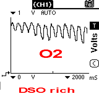
Note below, the meter on the left looks stuck, IT IS NOT! You must know your meter well, to trust it. The Voltmeter is connected to a good 02 and the DSO to bad reading, below.
If you must use a meter or DSO , connect that the 02 connector pins using backprobing methods, do not cut the wires.
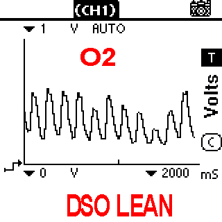
Left is a DMM set to DC volts. and Right is a digital Oscillisope.
Photo 1 DMM photo 2: DSO
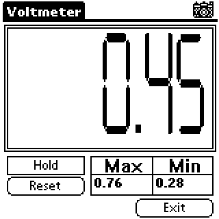
If a cheap meter don't have the Max/ Min window above .you are sunk.
So all you get is an average (like above 0.45) or a very fast wandering random reading. (it is an Alternating signal after all)
Slow meters will not average correctly (cheap meters)
If the cheap DMM meter samples too slow? (refresh) IT WILL just rolls the digits in a random fashion (some meters us a sample and hold circuit. so only show a snap shot of the voltage , which is , quite useless.
The DSO above, shows, the sensor is weak (or weak injection?) it is switching fast 3 times a second !, but is offset. lean.
There is one cheap meter, that does work well (if the 02 is good), and that is here for $25 (or less) A DIY KIT ! (it shows the average) (a Dot bar or just bar meter)
The technology:
One fast way to get back full economy, is to replace the front sensor(s)(single bank) or both front and V6 two bank engines. (let the rear sensor ,rot)
The newer ECU can report a stuck sensor. 1996 and newer easy, P0131 to P0175 DTC's
Or DTC 13 , on the old cars.
The reason ECU can't tell a 02 is weak , is because It has, no accurate standard, in which to compare that sensor.
If say the 02 is biased and show too lean when not lean, the ECu then trims to rich.
On the other hand if the 02 is biased, shows rich, when not rich, the ECU then trims to lean.
This will show up in LTFT , long term fuel trim on any scan tool. The LTFT uses the 02 readings, to report trim. If the 02 reads lean (false lean) then the ECU goes rich (wrong) and the LTFT will be large plus number ( say +30%)
The trim is really saying (pretend 16valve MPI) that the MAF is way off. The fueling is mostly MAF based, the MAF reports AIR and the ECU adds fuel (matching the MAF "mass air") if the 02 reports lean, then the MAF must be under reporting AIR?, and the ECU adds fuel to match.
The Fuel trim number is that added fuel, amount.(for this case)
If the 02 swings are good ,the ECU thinks it's good, (for true STOICH) but if biased this old sensor, the fueling will be way off.
The old ECU just finds dead 02 sensors. DTC 13, there are no trim alarms.
The Newer cars, 1996+ can report if the 02 can not hold longterm fuel trim. Limits, the 1996 cars have what are called limit rails. Per the FSM.
If the 02 is way off ?, the old ECU follows it off the the cliff, to the abyss. (like lemmings.) (bogging or flooding) 1995 and older.
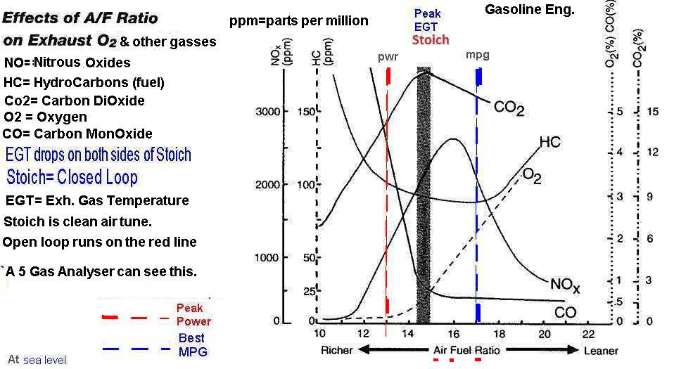
The below chart is a GAS chart, showing all the important gas relationships at different air fuel mixtures, ratios. AFR.
Note HC, 02 and CO2. STOICH is the act of burning every drop of fuel, wasting none. C02 peaking is that magic spot and zero smog.
See the drawing1 below, the ECU tries to hold the AFR in the center there.
If the ECU can not hold the "closed loop" state, the engine power or fuel mileage will suffer.
When accelerating , you get the red line fueling for max power.
When light cruising or idle , you are in closed loop. STOICH air fuel mix .
The right hand side of graph, is avoided under power (coasting is something else (cut fuel mode) the right hand lean side burns valves, or can cause feared Detonation The G16 has no knock sensor!.
Below are all the gasses. As you can see Stoich is dead center below.
When you drive W.O.T or with a fast right foot you get the Red dotted line.
Mechanics call this Stoich. as in are you running Stoich? is it?
Drawing #1:
 <Click me to zoom
The engine starts and gets up to full operating temperature.
The heated 1991+ O2 sensor can wake up after 20 seconds of running, and the ECU will use it at idle after this,and after 150F coolant temperatures are reached and fully at 180F +
The ECU tries to keep fueling correct any time you leave cold start, I allows richer AFR until, fully warm then hot. (this is all table controlled the rules for mixture at warm up.)
Closed loop drops out, on a cold motor, wide open throttle (over 75% throttle) or when accelerating fast.
Close loop is a state of being, where by the ECU can keep the air to fuel ratio at 14.7:1 (or as it seem fit for mode) Air to fuel (by weight) this gives the lowest smog and best MPG.
{14.2:1 AFR if running 10% Ethanol, aka: Corn Liquor) The ethanol causes the true readings to be off a very tiny bit.
Close loop means the ECU and this one sensor O² , work to hold the AFR in the center bar above , most of the time. Like an Autopilot on a ship or air plane.
The ECU contantly hunts this perfect AFR.
This causes the O² sensor voltage to vary. (constantly hunting for perfection, and other complex reasons, off topic)
If your car is old and has no OBD1 scan tool (as our pre 96's) then you must attach a DSO scope to the sensor to see this voltage and the swings. ( some fast analog meters can see this swing, but are iffy)
Nothing beats a scope.
Ok, what is a DSO, it's a Digital Storage Scope. The best bang for buck on a scope is the Tekpower CQ5010c
The O² sensor is not a real linear sensor, as one might expect, but is more like a switch, in that it can only say (read out) too lean or too rich and never can it read, how much is the error.
The O² only can tell the ECU Go this way or that way. (mostly) This weakness puts a huge load on the ECU to find the sweet spot. (google: Wide band O² for a cure)
The ECU is forced to jog the signal to find the correct mixture values. This is called swings or crosscounts in the business.
The ECU has limit rails (hard coded parameter in memory )) that limit how far any O2 can effect total injection rates. ( these software rails prevent dangerous lean and flooding conditions)
My experience shows , older cars will go way to far rich or lean, but the newer cars , limit this extremes and set DTCs for hitting the fuel trim rails.
Example, fuel pressure is way to high (pretend 55 psi) and injectors now horrible rich, ECU lets O² force max lean injectors, and rail and JAM THERE. Results , rich full time.
This happens because the high pressure (a big lie to the ECU) overpowers the Authority of the O² sensor. The results is less rich, but very rich non the same.
This is called Command Authority in the books.
The reality of on car 02 testing. (short and sweet) The off car test pass.
- If I suspect a O2 being bad, I just swap it
out for $35, 8 valve over 80k and 16v over 100,000 miles. (ash can it, gas is more expensive)
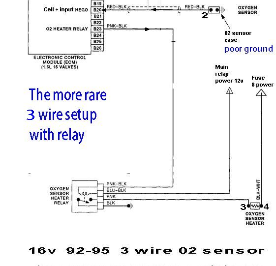
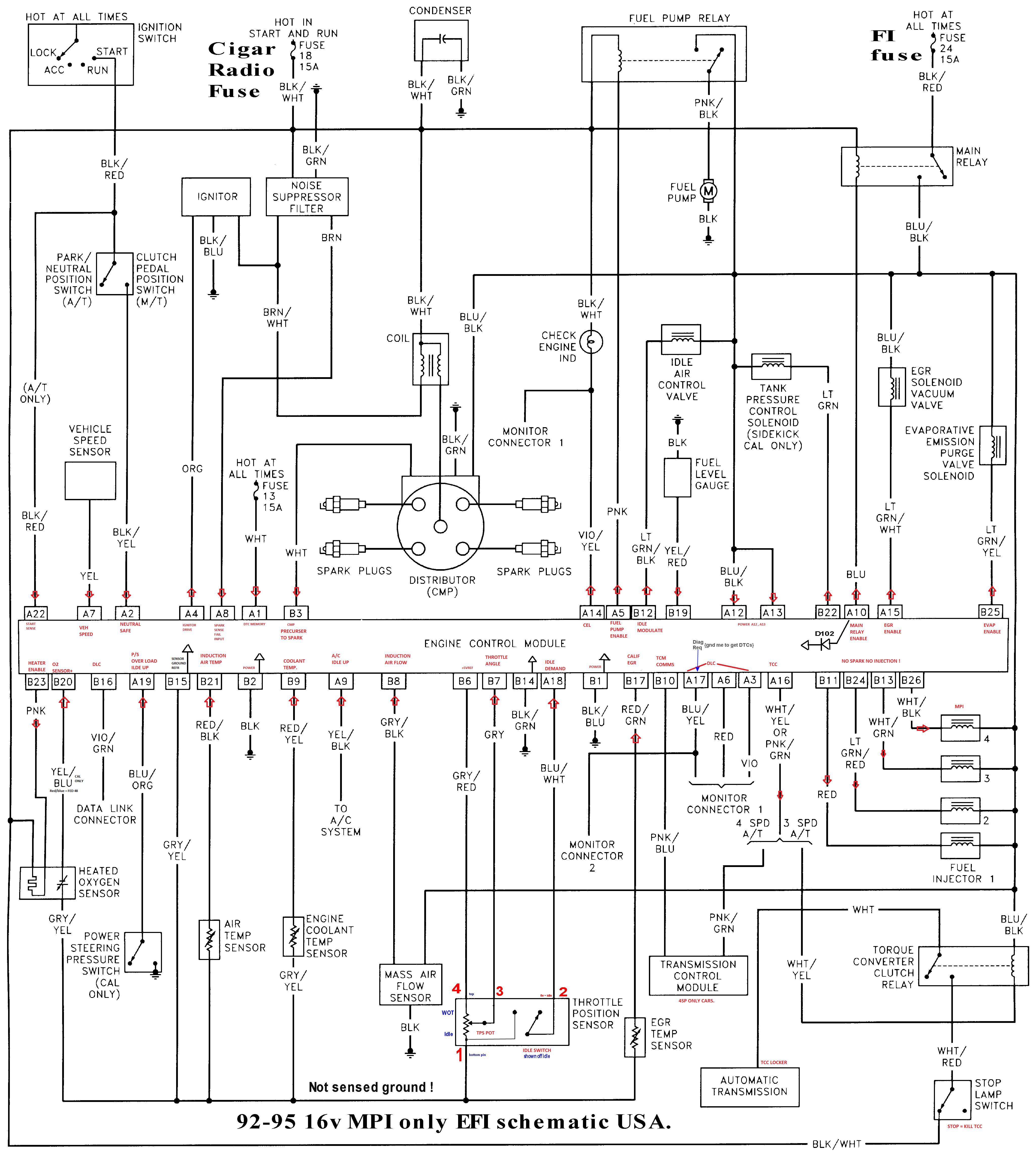
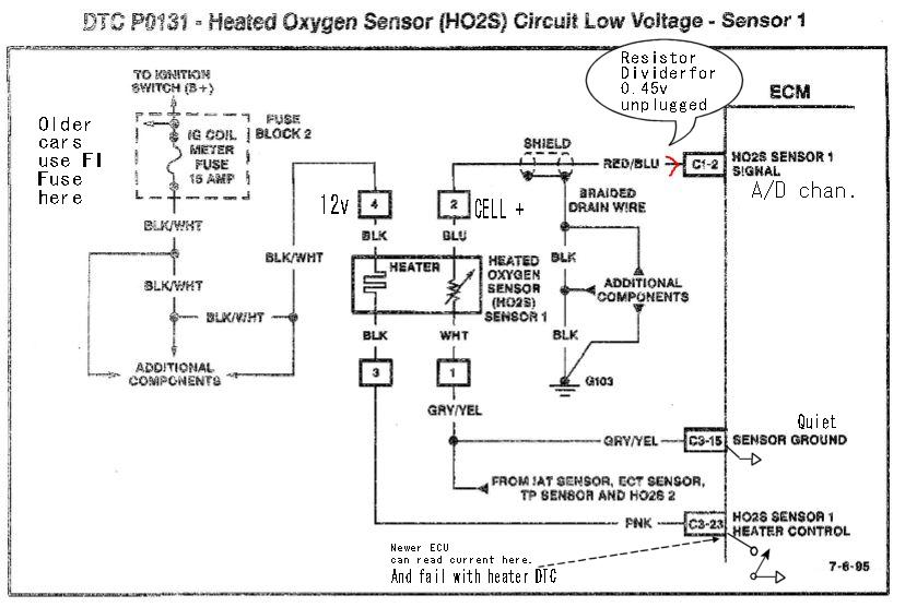
- Make sure the heater has 12vdc power. (use a voltmeter) Drawing 2 pin 4 and pin 3 is 0volts. (use the correct ECU drawings for your car here)
- Start car with scope (best) or volt meter with analog real
or LCD analog bar on screen , and connect minus lead to pin 1 and plus
lead red to pin 2. (scope probe tip to pin2)
- All kicks 91+ will enter closed loop and this voltage will swing and look like this, in
less that 30 seconds of a cold start.(heater
action)
- See the Voltmeter above at photo 1.
- Advanced ASE type tests below: (O2 shows lean as 0v and rich as 1v)
- How to force AFR is next (the air fuel ratio) FORCINGS: (forcing the 02 signals or waking it up) A HOT ENGINE at IDLE
- Force rich on all engines, with the
introduction of Propane gas
, at the air cleaner port. ( and not causing a vacuum leak from
MAF to Intake head valves) ( the 02 sensor goes rich, showing
less oxygen , voltage shifts lower and LTFT shifts more minus say -15%)
- 16v MPI rich by pulling the
FPred Vacuum hose (block the vacuum side fast with a golf TEE)
this dont work on any 8v. (it has altitude compensation ) Same results as above.
- To force lean state, on the 16v by causing any leak at the plenum ( I pull the EVAP hose at the front of the plenum tank) it sucks air like crazy and goes lean. ( the 02 sensor goes lean, showing more oxygen , voltage shifts higher and LTFT shifts more plus say +15% or more)
- To force the 8v lean ,is harder to do. (the MAP will not allow it to go lean) ( but FPreg. nipple?, if you apply vacuum to it, this causes fuel pressure to drop and lean with the results as the above and +15% fuel trim, trim rises Plus)
- We
do these forcings to see if we can wake up the 02 (from dead) or get it
to see my changes. Using a real scan tool works best, Keep
in mind the sensor sees the changes and the corrects fueing, and this
correction only shows up in 2 places, the LTFT and injection rates.
- The working system if you add exra air, the 02 shows that fast and the ECU corrects this now and the 02 goes back to normal. Quickly. but the LTFT shows the correction it made. LTFT means OBD1 or 2 long term fuel trim.
- Don't forget that you can unplug the 02 sensor and see the natural fueling rates. . You can do this to see if the 02 output is making fueling all wrong. (say and exhaust leak near this 02 or has a short inside from heater to CELL pin 2) (or cures idle gross misfiring?)
- Keep in mind the 02 real job is to correct for MAF
inaccuracies, or say slight errors in fuel pressure, and partially
clogged injectors, but will not do that accelerating. This hint
here is a great help in diagnosis.
The MAF will cause lean running if the MAF is coked up. (it eats dirt all day and makes gunk on the hot wire and cokes up ) clean it.
More minus LTFT means the EFI is Subtracting fuel.
more plus is adding.
Our number 1 job is to see if the O² swings.
Failures to swing:
An O² stuck high or low (or in middle ), is caused because it's bad, or the ECU is faulting ( or lied to) and motor is fully rich or lean and the ECU can not recover, do to many reasons...)
There are tests to discover this truth.
- The things to look at here are:
- Stuck low
- Stuck high
- Not swinging deep enough , bad O² . (see last photo for proper DEPTH)
The O² sensor can pass all tests and be bad, if it is biased. There is no way to check the accuracy of the O² so you must change them out at 80,000. USA odometer Miles. < Best Practice !
The O² sensor is free if you consider the price of fuel real.?
LEAN RICH.
The above DSO photos happen for 1.5 seconds. then recover to normal.
I created a vacuum lean (pulled the EVAP nipple on plenum) and the DSO LEAN happened for 1.5 seconds, then when normal like the below photo shows. (will NOT work on 8v with vacuum leaks)
I then made the motor rich with propane introduction at the air cleaner, shown on the right above , it lasted for 1.5 seconds (approx) and the ECU catches up and looks like the below.
If you find the readings above stuck at the rails ( zero volts or near 1 volt) try everything you can to force the opposite condition by adding air or fuel as appropriate.
You need to find out if the 02 is even alive?
You may fail, if the problem is extreme or the EFI ECU is stuck in limphome , limphome cancels, Closed loop.
In the case of a stuck closed , Fuel Pump regulator the O² will RAIL high and no tricks may stop it !. Unless you pull the brake booster hose. ( a huge air leak might drop the rich reading?.)
The 8v motor you need to play with the MAP signals to get the EFI to do what you want. (a hand vacuum tools does that)
Trick 2 on all 16v motors is to pull the Fuel pump regulator vacuum hose (plug it) and the fuel pressure rises 10 psi and motor will go richer. ( I use this trick and the propane trick)
Starting with a new O² , makes troubleshooting vastly more easy, because you trust it and know it will respond to your bidding and that you can use it to find out if motor is rich or stuck lean.
Just because the O² is stuck does not mean the O² sensor is bad.
This page should put you on track , is my O² bad?, or is my ECU being lied to by other factors and sensors?
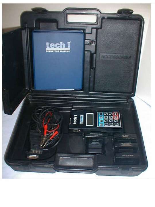
The only OBD1 full scan too,l that can scan a pre 96 Suzuki are as follows:
Used by GM and other shops. A rare tool and very expensive Tech1.
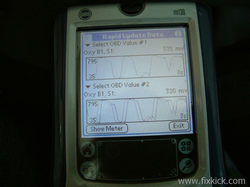
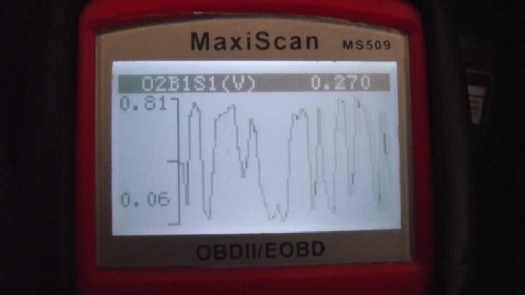
Below is what the O² looks like normally;
OBD2 makes it so much easier. (no DSO needed)
The horizontal axis is TIME.
Basically, this O² is swinging from near zero volts to 0.8 volts. And IS Good to GO.!
Scanning real fast my front O² sensor: Bank 1 Sensor one, the front sensor. This is what the ECU sees live for this OXY sensor.
The signal here is a bit choppy but that is because the ECU is slow to see each swing and report it in time. (or the scan tool is slow) It dont matter., I can see its swinging fast, and to the correct levels.
Great reading on topic ! Highly recommended , the below links .!
Oxygen sensors crash course and myths.
Popular Mechanics Mag.
A real good deal on Sheffield ST05 Oxygen Sensor Tester
See my V6 02 sensor swap page for the horror of the V6
O2 sensor unplugged tests Aka, Bench tested.
Never use a Resistance meter OHMS scale of DMM (has power to the leads) to measure the CELL pins (paired) of any O² sensor. Cell plus to Cell minus
I'll mention all tests with the DMM (ohms) and exception to above statement.
This waring is because old meters and for sure old analog meters used high current and voltages to test resistance (ohms) some as high as 22vdc (old relic Simpson 360/370s are classic and a huge danger to electronics)
Modern meters are mostly safe. (they use very tiny voltages 0.2v and very low currents microamps.
Do not check ohms across the CELL pins (cell plus and minus wires) but is ok from CEL to body or CELL to heater, to find CELL shorts to heater.
The 1989-90'car , has a 1 wire sensor, keep the ohm meter totally away from this sensor with no hearter.
More Ohms tests that work.?
There are 3 wire and 4 wire, sensors, the 4 wire have 2 ground wires SEEN HERE. that allow me to check the CELL + pin to both heater wires safely. expect infinity.
The 3 wire is more tricky, so check the heater hot wire 12vdc pin to the CELL Plus wire for infinity. The 3 wire , sensor the heater is grounded to the sensors casing. The CELL minus pin is a quiet ground to the ECU. and is isolated)
To test the 3 wire sensor , check for ohms (high range) from CELL Plus to CASE. If not infinity the Sensor is bad.
The heater wires will read about 10 ohms, if not the heater is burned out. The 3wire heater is at the CASE and the 1 heater wire.
The heater test is 100% safe, but the 3 wire the heater is connected to the case, so there are no heater to case leakage tests like the 4 wire.
The O2 sensor has many failure modes.
Never cut the wires,on any non generic sensor, many brands of sensors breath via the wires, in a very odd way, do not cut the wires on the OEM PNP sensors. (for sure close to the body) in the same way, do not cut the univeral sensors wires shorter. (do not)
Never use solvents on any 02 of anykind.
Drawing 2: 1996. 4 wire 02.
Common failure classes:
- The Heater is dead, is the most common failure, ( the normal heater current is about 1amp, if zero it's dead)
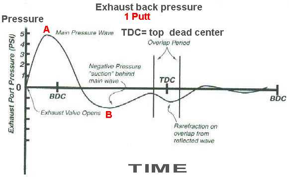
- The header exhuast is cracked or flange gasket leaks and sucks air due to the fact that after each exhuast PUTT the pressure inside goes negative, and will suck AIR, at 20% oxygen and the 02 will read WRONG.
- The 02 was run over 100k miles, and is dead, weak or poisoned or bias (lies)
- The wires to it are melted due to lost clamps there, allowing the wires to HIT the 2000°F exhuast parts.
- The 02 can not really be tested, (for accuracy) you can only test it to see if it is alive. Nothing more.
Happy Trails to all.
rev 6 ++++ 1-20-2011