The Throttle Position Sensor, or TPS testing (theory).
TPS idle switch Calibration G16’s , J18/J20 engines.
What is it, what does it do? (got symptoms?)
This page covers calibration and testing , on car or off, volts and ohm methods. (all ways)
The purpose of this page, is to save you $250 for a new sensor and show the test and calibration steps.
We must first discount, some the nincompoop’s reasons to mess up (or bad luck) the TV or TPS indexing: See JARGON here
If they messed up the TV stop screw , here is the easy fix (see my crude solutions here)
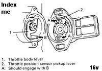
INDEX: (all G16 unless stated otherwise) All years are USA generations, not worldwide!
- What is it?
- Early 1989-90 8valve TBI , TPS Calibration (the most difficult to get right)
- Fast 1991+ TBI Ohms checks. (in fact this check works on all G16 engines, only the pins vary)
- Late 1991+ 8v TBI live voltage testing.
- Last 1991+ 8v TBI, and newer TPS Calibration procedures.
- 16v TPS Testing only. (92-98′) MPI
- 16v TPS Calibration only. (92-98′) MPI
- The multi-engine Feeler gauge matrix Chart: (vary handy, once you know how to do CAL, this is all you need)
- How do TPS fail? (lots of ways)
- The fix for timing freeze TBI is here. (static spark timing steps fails , as seen here.)
- The fix for timing freeze fail MPI is here. In many cases the timing freeze can fail for these too.
- 3 TPS bench tests here (video’s).
- Those nincompoops? or hackers messed up my car? Things that gone wrong!
- My list of symptoms.
- Make sure your DMM meter is working ok , first. How to use the DMM.
- The J18 SPORT ENGINE (and J20 ) is set to 0.5v (easy peasy! no more stink’n feelers , no more removing TB to get at the GAP!)
What is it?:
The G16a/b TPS, has 2 parts, It is Ganged ! 1 Throttle Angle Pot. and 1 Idle Switch inside.
Myths:
Throttle Angle: (the Suzuki TP pin)
Myth#1: (all comments on a Hot engine)
It is not the device that determines, fuel rates (flow) at idle, cruise or WOT ! There are exceptions to that.
The angle side never sets idle speeds, ever. (but the idle switch , yes idle will be wrong if the switch is dead.)
Angle does change fueling rates (fast acting throttle only) with a fast moving right foot, “acceleration beginnings” It prevents hesitations.
The TPS is the key sensor (instigator) to Enrich mode, that ends STOICH air/fuel/ratio , entering Enrich mode, as seen here.
Flow rates are determined primarily by the AIR meter(MPI) or MAP(TBI) , the ECU sees air flow into the engine and matches measured AIR, with proper injections.
By the way, if idle speed is out of control ?,with the switch closed (0-volts) is covered found here.
This page covers calibration or testing the TPS.
The word Pot. means potentiometer or variable resistor.
The Suzuki named TP pin is called throttle angle today. (ASE/SAE) (ISO, I’m clueless)
The Angle pin is used for fast throttle enrichment detection and to detect cut throttle. It is not a precision voltage or ohmic reading. (despite vast myths)
The Angle pin only needs to be linear, (foot action to Ohms(volts) It must not glitch as you drive. ( it shows what your right foot is doing, only)
Sides:
Side 1, Idle Switch. (this switch never produces 0 ohms, but does go below 300 ohms for closed , ECU expects less that 500 or less, we think) The J18 engine first removed this device and on all future engines.
“ON” means the switch is closed (very low ohms ,Typical. about 50 ohms or near 0volts) OFF means the switch reads, Infinity. ( resistance meter){ near 5volts}
The switch most work right or many features fail, like timing freeze (service) or idle controls are dead or EGR fails to work, and the ISC goes dead.(idle speed controls)
Side1 is the calibration pin.
Side 2 Angle side, the Pot. side called by Suzuki “TP” pin, is the Throttle angle pin, and allows for the ECU to enrich fuel with a fast right foot. (and many other functions related to this pin)
The Throttle angle pot is a crude 5,000 ohm(3500- 6500 ohms) Pot. or potentiometer, or variable resistor. It is a passive device, no electronics inside, only carbon . Angle is never calibrated.
The ECU sees VOLTS on this pin, and watches for fast changes to the voltage and never (cept cranking) uses the exact voltage to do anything. (my comments are on a normal hot running engine)
If this pin fails, for any reason, TV cables (up to 3 cables) not set at 10mm play, or TV bore blocked in carbon, these faults must be cleared first or the Calibration steps will all be wrong.
This same pin if failing for any reason will cause the Spark timing freeze ENABLE to fail too. (timing jumps during static timing procedures?)
The TPS angle pin is watched by the ECU for the drivers fast moving right foot. (Accelerating he/she is?) The ECU goes rich, from STOICH mode, and lasts only long enough for the MAP or MAF sensors to catch up.
So that means if say , engine power is lost and never catches up?, then the TPS is NOT THIS PART BAD. (myth debunked) The exceptions.
All EFI engines like this go lean if the driver punches the throttle, all do (dead TPS), ( due to that slug of air is INSTANT) then the AIR meter sees the change late. this late discovery causes lean bog and self corrects.
The TPS Angle checks, prevents this hesitation; that is it prime job “Enrich mode“. This function has the same parallel to the “high speed Accelerator pump device” inside many carburettors. Omg what is a Carb?
This lean slug of air, must be instantly fed extra fuel or the engine will bog (go lean) as the driver moves his foot fast on the throttle. (we can’t burn air), ergo the TPS angle pot was invented.
DTC’s? Diagnostic Trouble codes:
The ECU checks for errors (DTC) on the Angle side., or wires cut to it (cut means , really cut “broken” or any connector in this path RUSTY) (rusty , corroded, broken pins, bent pins, smashed ,etc)
If the ECU shows Idle switch bad (DTC) that is usually, just not calibrated caused. (The TPS is bad, if the calibration fails, and the wires to it, are good)
To see more facts and theories. on TPS look here.
First trouble maker #1: The DP or “Dash Pot”. (it is just a vacuum servo motor, a vacuum “actuator”
This TBI 8valve device (back side of Throttle body) must be retracted someway to do the TPS calibration.
NO MPI engine G16B has such a device.
The FSM instructions, are are linked in every section on calibation and does cover this step.
The TBI only, Dash pot, has a spring inside, and pushes outward that plunger by default, and holds the throttle open with keys in pocket! (causing the idle switch to open , making calibration IMPOSSIBLE)
What you do is: (3 ways to joy?)
- Use a hand vacuum tool to retract it for calibration. *(8 inches HG vacuum dose it) at nipple seen below.
- unbolt that nut below (stud) and remove the DP for calibration.
- use tie wraps or bailing wire to tie it back some way.
- Holding it open by hand is no fun with DMM meter in other hand… unless you are octopus man.
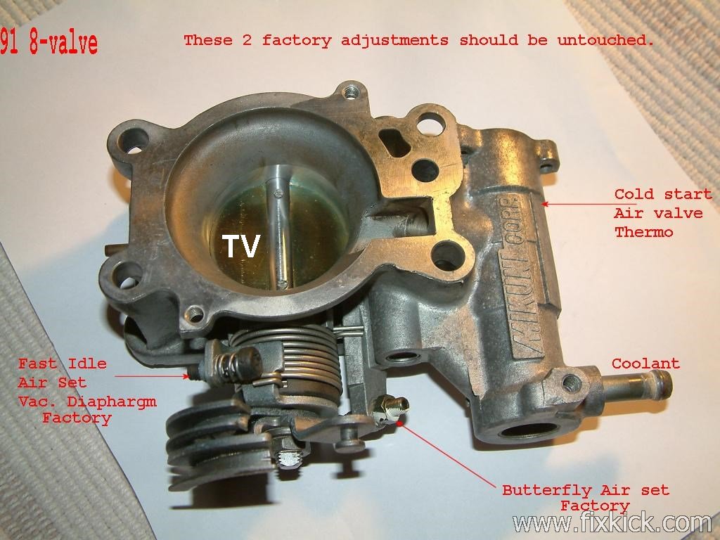
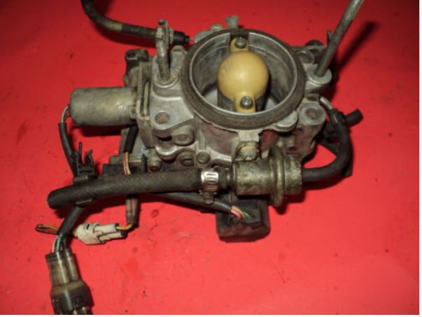
Photo #1: (aka. the cold start fast idle device ) The VSV (vac. sol. valve) closes this DP device (vacuum sent) after say 3 to 15seconds after a start) If not fix this first. (tie it back, to do the Calibration works)
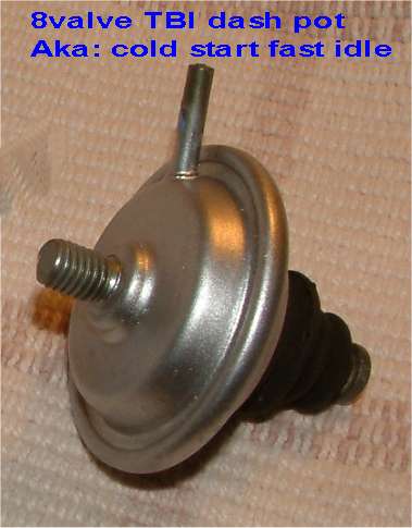 G16A TBI 8valve only device found on TB (throttle body) this device is only vacuum motor (servo) Just a diaphragm and spring inside.
Seen more clearly here.
The dash pot is the cold start, fast idle device, (short duration 3 to 30 seconds (30 is in Alaska)
CALIBRATION GAUGES : 10 years of methods and values.
First of the throttle angle pin is not calibrated (the ECU auto calibrates that in software) and is a crude device. The idle switch is the only device calibrated here.
The TBI engine G16A dash pot device must be retracted first !
Go, & NoGo feeler gauge chart: Suzuki in black ( with odd GM deviances) USA FACTS !
The 8v is a TBI , throttle body injection a.k.a. SPI Single point injection, by some. ( except some 1.3L Carb. G13 engines, do not have EFI , so hit the back button)
The 89/90′ TBI is a very hard car to adjust, because the Idle adjust screw(stop), changed at ANY time?, wrecks the TPS calibration (Suzuki corrected this pain, in 1991, folly?)
MPI 92 -98′ 1.6L only USA. MPI is 16v Multipoint Injection motors, and has no Dash pot steps, or device.
This table was made from real USA FSM data.
WARNING: THE DASHPOT DEVICE MUST BE RETRACTED for all TBI, on car checks below (TBI is 8valve engine)
(tie it back, suck it back or remove it.) (suck means, use vacuum hand pump tool) or remove the DP with that single stud screw. (TBI G16A)
All tests are done keys in pocket. Key off.
The Feeler gauge Matrix Table 1: (created from all origional FSM manuals (factory service manuals) Suzuk and GM.) I have the only list like this in the web.
(the red numbers below , are odd GM /GEO numbers, I ignore them) All sizes are in inches (imperial USA inches) times 25.4 for mm.
| Engine | 1.3L TBI 1989 (rare) |
1.6L TBI 91 to 95′ | 1.6L MPI 92 to 98′ |
1.8L Sport DOHC |
89-90 TBI |
Ohms |
| CALib. | .012 | .016 | .026 | 0.5Volts | note1 | Threshold |
| NOGO | .016 | 0.20 (.035) | .037 (.031) | N.A. | none | Infinity |
| GO | .008 | .012 | .020 | N.A. | none | closed. |
Idle switch OHMS. (over range, on the meter , means Infinity , and that is what causes, DTC-44 flash code errors, at idle. lean what infinity means by setting meter to 2k (200) ohm scale , with leads held in air. +1 flashing? (varies by maker of DMM)
The idle switch (pretend 91′ G16a) shows infinity ohms with throttle open then when .016″ gap (.4mm) happens the OHMS drops to 500 or less like a shot, some do this at 1000 ohms, we calibrate near 500 but is crude, just get it below 500, a touch.
I have seen new switches vary from 50 to 1000ohms (in the first .030″ of travel.. the goes to infinity (and open circuit)
Closed means less than 300 ohms. (is goal , 500 is spec. in software we think, so use 300 for best upper limit)
Open = infinity, (meter shows , infinity ohms)
Threshold is setting it, just so the switch has just closed.
If you removed the TPS and didn’t index the body TPS pins to the TPS actual pin sockets, none of this will work correctly. You may cause the throttle to stick open.(a danger)
Keep in mind, when you set the .016″ setting (example) you then remove the feeler , and the throttle retracts .016″ and you get a solid repeatable less than 300 ohms each time. < with good skills you can set it with one feeler(calib). and it will work.
GO = Closed IDLE switch ( less then 300 ohms) (300 ohms is TPS spec, , ECU spec, i think is 500) I use 300 ohms. (for sure ,300 to 500 range works )
This is no gold contact switch, it’s only CARBON!
It will never read zero ohms ever, like real gold contact switches would. (some cars not this, one use real switches and many Technicians, know how those works, and my comment)
Infinity resistance ohm, is open = ( meter DMM displaying O.R, over range, or O.L, over load, see your meters operational manual, some show over range in different ways)
NOGO= Open Switch. (Infinity)
If your meter is a fixed range meter not auto ranging then ,use the 2000 or 2k ohm range. (if the auto ranger shows 2.01 K that means near 2000 ohms, K means times 1000.
if the Auto ranger shows 0.300 k that is 300 ohms. see? the K shows up on the LCD display , or omega sign or M for million. (your meter manual shows these facts)
CAL = Only the IDLE switch side is calibrated ! and CAL means you get the switch to just close, and you stop turning the TPS body. aka, set at threshold of closure.
The switch side is a bit strange, let me explain.
The Switch side Low ,will vary from about 20 ohms (50 ohms is par) to 300 ohms closed (experience) and then go to open circuit, very soon ,as you crack the throttle open just slightly.
In most cases 50 ohms to 1000 is the range on the switch carbon (real hardware) then jumps to INFINITY about .030’_ travel off the stops, The only reason this is hard, is the silly carbon cheap Suzuki switch. (on say a Toyota ,we set it to 0 ohms)
The reason 3 gauges (feeler) are used is to compensate for human errors setting this switch. (non 89-91)
If you get this wrong , the engine RPM , may surge & THROTTLE TIP-IN acceleration will hesitate ! ,due to, too late IDLE drop out or too early idle release,. Code 44s, and timing freeze fails to work (the jumper)
NOTE 1 Exceptions: G16a TBI EFI 1989/90 ONLY using these special steps only.
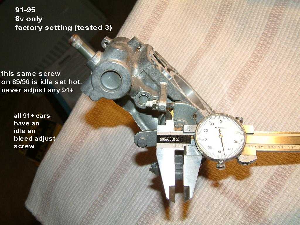
1989-90 Note 1: (old kicks use only 1 gauge , FSM)
This car , this year, this TB, this calibration, destroys idle speed calibration. So be ready to do that 2nd.
THE CAL feeler gauge: choices: M/T is 5sp manual transmission. A/T is automatic tranny
0.086″ M/T we say in the business 86 Thou ! (yes , stack the feeler gages)
0.094″ A/T (nearly a 1/10 inch !) huge. huh?
Rotate TPS fully clock wise, then CCW gradually until C to D switch JUST closes.
There are no , GO or NOGO gage tests, for these 2 early years. So calibration can be harder.
The DP must be retracted.
Yes, setting up 94 thou , is a pain, no feeler gage set has this size. I had to stack some feelers to get this.
BEGIN TESTING the G16A, TBI engine 1991- 1995: (8 valve , engine only) The 3 video tests (mp4)
In the USA the TBI engines were banned in 1996 by EPA and C.A.R.B. edicts.
See very different 1989/90 G16A.
The 8V factory TPS data pages:
This section is NOT CALIBRATION ! It is just some quick Checks,looking for the hard fails first.
The dash pot device must be retracted engine running.
This is the Fast ohms tests, unplugged tests.
We do the 4 TPS tests below first, before Calibration steps here to be sure its even working at all. If all is good, we can skip the calibration.
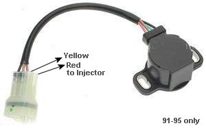
Photo 2: TPS (TBI G16A only) This TPS connector shares the injector connector. 1991+
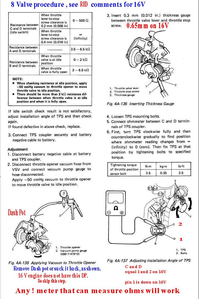
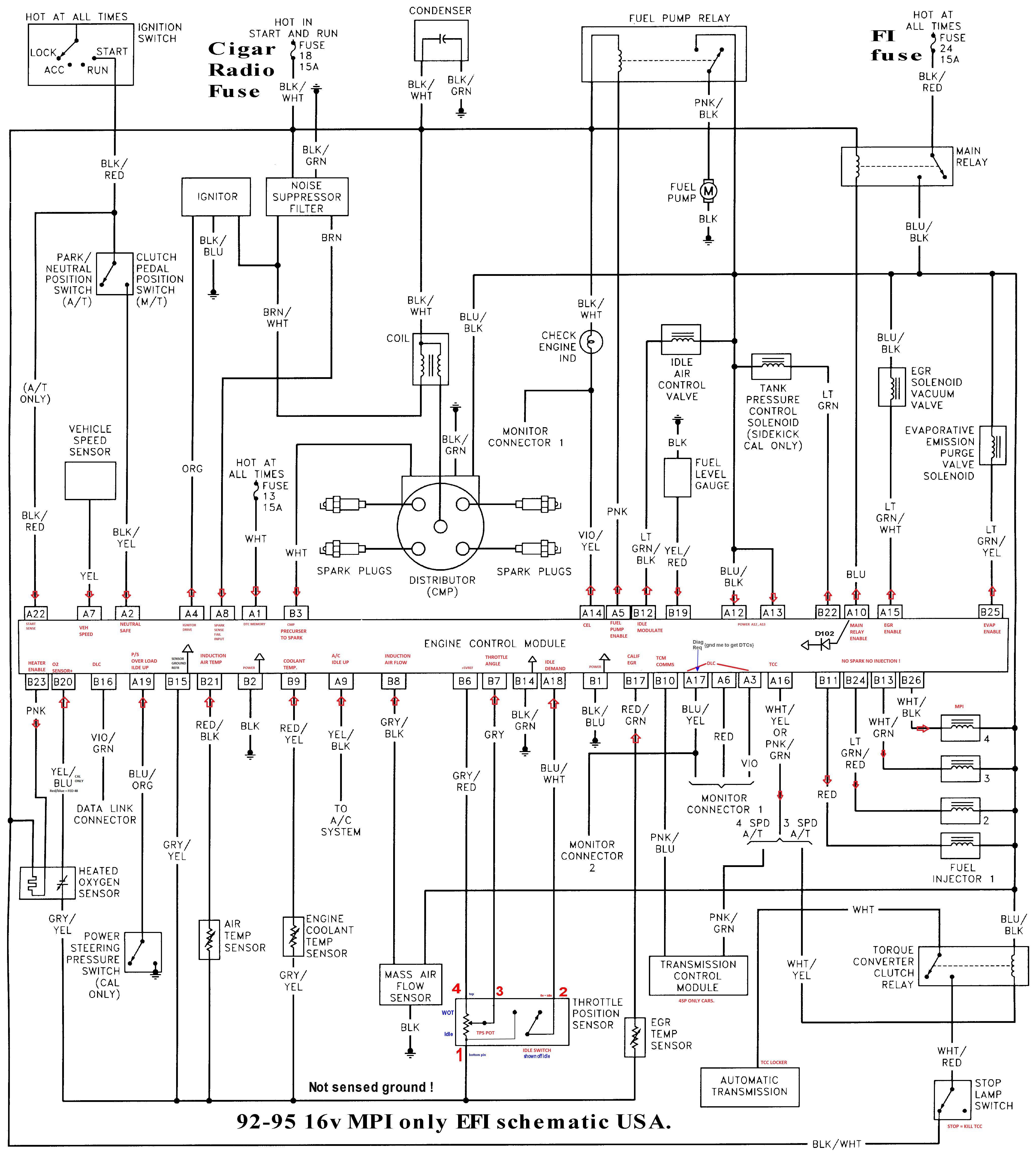
Graphic 1: You can do on car voltage tests, or simple ohms (resistance )test.
FYI:
The idle switch must be closed and near 0v running or the timing freeze or EGR, ISC will fail to work and DTC 44s happen. (89-95′ years)
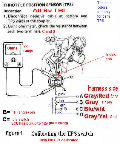 Figure1
Fast nut shell testing: (Unplugged) 1991 to 1995 TBI. G16A.
Note now that the main resistor A to D is very crude, its not precision at all, so if yours reds 4000 ohms and steady , then that is what it is. NORMAL. steady it must be. (using 20k meter range) never reads infinity.
Set meter to 20k scale. Ohms. (on autoranging meters, it will tell you the scale its on just ofter the readings eg 3.5 k, means 3500 ohms the “K” ICON on the meter LCD means , times 1000)
I check ohms for 3500- 6500 ohms, pin A to D. ( it’s very crude) It must not read infinity or the TPS is no good. (the reading of 4.0K is 4000 ohms.)
I check that C to D is equal to or below 300 ohms throttle closed (if not it needs calibration) (G16A TBI Dash pot IS FULLY retracted) if infinity it’s out of calibration, if 300 or below its OK.
Meter to B and D ,(throttle angle) ohms varies from about 1k to 5k ohms (this angle and resistance, is crude!, but it only needs to vary and not glitch. The TPS angles are not calibrated. (by people)
Meter to A and B, the same as above but in reverse actions. (the ECU does not use this way, but I check it so I can find glitches not found , B to D.)
End fast testing. (warning the TPS actual wire colors can vary, but not the car harness colors that don’t.)
Side issue?
Even better is a scope on pin, B , testing both for glitches, as you advance the throttle, a TPS when worn, loves to GLITCH !
Most TPS devices last for 150k miles or more… lots more and are very expensive to buy… so the testing is well paid for… if it passes, tests…
A Live on car TPS voltage test: TBI only.
One little secret that helps understand the TP pin (throttle angle) is that the ECU TP pin has a 470k ohm pull down resistor inside ECU so that if the TP pin goes open the ECU sees 0 volts (for safety)
This fact also explains why the GLITCH, if any, also causes the glitch to drop to zero volts. fast. Hint watch for drop outs.!
See figure 1 above, for pin Identifications. (I will use harness side colors, because they do not change) This test is long, but is better than guessing and paying $250 for a new sensor !!
Do not disconnect the connector, until you wish to do an OHMS test, above.
VOLTS TESTING: using any needle or back probe meter lead set.
Key ON: No start (we will measure, the 4 pins live and hot, and use back-probing method) All connections, normal, no disconnects!
Any voltmeter can work here, even a $10 one. (Walmart)
Setup 1:
Set the DMM voltmeter to 20VDC range, and connect the minus (black) test lead to the battery, minus lug , for best results. (or to the engines shinny metal) For a ground reference.
Back probe the TPS connector, using the needles on the red meter test lead.
These simple tests follow below: The Dash Pot must be retracted , when stated.
Test 1: Pin “A”, power pin test. Key ON.
(+5 vdc is applied to the TPS pot pin “A”, from ECU, if not , ECU is bad or this pin “A” wire is grounded out.. or cut) 4.75 to 5.25vdc is factory spec..
Test 2: Pin “D”, the ground pin test, it must read 0 volts , zero volts 0 to 0.5v . if not the ground is bad. (This cut wire,etc)
OK, the TPS now has power !
Test 3: Pin “B” is throttle angle, or a.k.a. the TP pin. for throttle pin. (mine varies from 1 to 4v with right foot action or hand turned TV valve. The voltage tracks my foot throttle 1:1 that is direct action and linear…)
If the pin is stuck , the voltage does not change, the TPS is bad. (or the wire on this pin is shorted to ground or to the power pin A)
(if this pin fails?, hard, the ECU may go to Failsafe mode, Sets DTC for TPS , if it glitches No voltage Jumpiness or drop outs allowed!
Pin B (TP pin) below, the voltage will very, for near 0v to near 5v, as the throttle is advanced. The Advance must be smooth.
if this pin drops below 4% throttle angle (below about 0.2Volts) driving, you will get DTC codes 21/22 errors. (I’m not sure which DTC # is which)
The voltage will rise to at least 4v (5.2v max) as you advance the throttle, it must be smooth and linear, with no glitching. (wild jumps or drops in voltage)
Pin B (TP) (see FSM here) ( the normal voltage idling is 0.6 to 1.5v )
Pin B must not be stuck at 0v. it must not be stuck at 5volts. Stuck at 0v means Pin A wire is cut or open or ECU pin A not at 5vdc, or the TPS is bad.
Pin B stuck at 5v, is caused by a bad TPS or the ground wire broken. Pin D is Cut or the TPS is bad. (cut means broken,cut or corroded)
Pin B, voltage must move, and be directly proportional to your throttle actions ! ( as you vary the throttle (with hand or foot) voltage must be linear and smooth at Pin B )
FYI:
The only true 100% accurate TPS throttle angle test Pin B, is with a scope, to see all glitches.!!!
Any DMM‘s meter can be very slow reacting, and miss them.! (however an analog meter may see them or a graphic GMM may, and all scope for sure can…)
Test 4: (the idle switch tests, after getting DTC 44 and 45?, (stuck low, or stuck high , respectively)
We now test the TPS switch PIN. Pins C . TBI idle switch test, live !
TPS is connected to its harness.
Keyon, NOT RUNNING test:
Dashpot must be retracted by hand, during tests, any of 3 ways. (hand vacuum tool, tie it back, or removed (hard to do).
Connect volt meter just like above at setup1.
Back probe pin C. (at factory side, blue-white wire, ) This is the calibrate pin, and we are only testing now, not Calibrating yet.
If the idle switch fails, the ECU will not allow idle speed controls. (on other features keyed off this line, EGR enable, and doing spark timing the freeze jumper fails to work.)
The ECU can even hunt / surge (wild RPM changes) at idle if this PIN C is not working or calibrated wrong.
If it stays closed too long, the ECU will fight you, as you tip in the throttle , one of the most odd sensations in car, you will ever experience, here)
Begin tests:
I probe pin C ,key On no start,, and the “Dash Pot” is holding the throttle open now, (if not fix that now) and the voltage is 0vdc, (± 0.5v)
I then drop the DASH pot, arm and the throttle opens and the PIN C goes to near 5 volts, (closed switch )
You will not get perfect zero volts, just very close.
0v means idle, 5v means not idle. ( I corrected and error here.. shame on me…)
If You can’t get zero volts (or near) the throttle is blocked open by something or the TPS calibration is way off, or the TPS is bad, at Calibration proves this out… later…
end test 4:
Predicates:
A bad idle switch makes calibration , impossible. (if it can’t ever close)
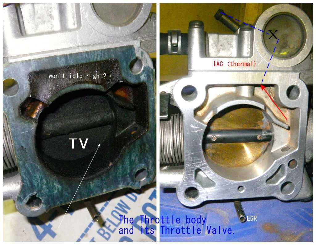
In side the TB , Throttle body is a Throttle Valve, TV.
Eg.: any of 3 throttle cables set tight, TV,cruise and A/T kick down cables (set wrong) The spec. on those cables is 10mm slack. (7/16″ inches)
The TPS must never interfere with the TV or the opposite. The TPS must not prevent the TV from closing 100%. ( the “TV” is the Throttle valve.)
The cables must never be tight and holding the Throttle valve open (TV) at all.
The TV must not be packed in GUNK causing TV to not fully close.
Only the Dashpot on top left of TB throttle body, is allowed to do this. (keyon or off , not started)
The TPS can be mounted wrong, and blocks the TV open.
end on car tests.
BENCH Glitch TESTS?: (off car tests)
AKA: throttle angle tests (TBI G16A example)
It’s no different than on car tests, with connector pulled off, and again the DASH POT must be retracted on the G16 TBI body.
The TPS can be tested on a bench too. (example of throttle angle testing and finding dead spots or glitches)
This tests can find a bad throttle angle sensor portion. (using just a cheap SMOKE detector battery)
BATTERY from A to D (plus on A) connected directly then add a resistor from B to D(minus battery side) this simulates a real ECU load.
By using power supply and a 470k ohm resistor from the TP pin “B” to “D” ground.(called a load)
(use a 6v, 9v or 12vdc battery as your supply , or a 5v power supply , really 3 to 12vdc works. )
You can even do so with a scope to see if the TPS glitches, It can be near tested 100% with proper tools.(and patience galore) Scope on pin B .
Connect a battery of any kind, to from pin A do D. (pin A is plus pin) (using any cheap 9v smoke detector battery works)
Then put a load resistor 470k (yellow,Violet-yellow color code) on Pin B to ground, (resistor side one at B pin and the other resistor end to ground pin)
This works on all TPS sensors, only the pin names vary. See the schematics here.
See graphic1: (a bad indication is the falling (negative ) spikes, called glitches. As you turn the throttle up or down.
Put the scope probe to pin B and D. Scope shield ground clip to D
Turn the TPS center shaft and see that the voltages are linear and that they never glitch. (or have dead spots as you turn the throttle shaft).
Seeing this aberrant glitch with some DMM can be very hard, as they are so slow to measure, and can miss the glitch. (the glitching can be VERY fast, 20/1000’s of second )
When driving the ECU may ignore the fast glitches but all get worse, in time, and if you see it glitching you know for sure that the duration can very (made worse) by the engine vibration…
The ECU will not set a code for Glitches. (pin B) (it just acts up, (enrich mode or cut fuel on the fly, when at steady cruise, will be ugly here)! Bucking or misfiring (rich)
The ECU watches for legitimate fast throttle angle changes, and when it sees them it BELIEVES them (A.Turing brain,mind set) and that they are DRIVER CAUSED. (thus real, and no errors set)
(takes human testing to find this flaw, the ECU is very dumb here)
Warning, (TPS calibrated to open late)
if the TPS delays opening, the idle switch , as you move the throttle pedal, a tiny bit ( .020″) The ECU and ISC will fight you hard, and it will SURGE during that fight. A Very dangerous car to drive !
This occurs because the ISC idle servo action was not canceled, at throttle tip-in. Very bad that. (the ECU idle serve fights the drivers actions)
Normally what happens, at ECU pin A14, it is at 0v at idle, then the driver moves his foot .020″ (as measured at TB TV valve) and the idle controls are ended (canceled fast it must).
If not, all hell breaks loose with the driver (Max Surge) This is why we use the all 3 feeler gauges for calibration.(to avoid this nasty EFFECT)
If the ECU Pin A14 blue-white wire grounds, to the body of the car , the car is DANGEROUS ! (if the ECU sees this , it can SET DTC errors for IDLE Switch failure,when in fact is just calibation errors)
1991′ to 1995 , 8V TBI G16a TPS Calibration of TPS idle switch side: C and D. The 3 video tests (mp4)
(all years 8v) (this procedure assumes the TPS is not bad and that it was installed correctly , Indexed ) SEE 16V Calib. here.
See 1989/90 procedures here and quite unique.
Again, the 3 throttle cables (up to) must not be tight. they are set loose per the FSM. (cruise , throttle and a/t kick down cables)
The TPS on some cars can be removed and inserted wrong, effectively making the TPS DEAD. (not indexed to the body correctly, per the FSM)
Any ohm meter works, here, even the $10 Walmart meter, works very well. No need at all for expensive tools to do this very simple calibration. (even and old analog needle meter works perfectly)
If may steps below are not clear enough then the Actual real SUZUKI FSM is here.
Preliminary setup: (have the 3 feeler gages in hand, or stack them, only 1 feeler is needed to do just the CAL. (the others are for validation steps)
This method is called GO, NOGO and CAL. (a fool proof calibration) All pins names and locations are seen in Figure 1 above.
- Ignition Key is OFF.
- Retract the DASH-POT device , (use hand vacuum pump, remove the Dashpot with the signal stud nut) (I then look down the Throttle air horn and be sure the brass yellow TV valve is 100% closed, if not?, all this is hopeless.)
- Loosen the TPS mount screws. a tad, so the TPS can move easy, and rotate. See photos, at end of this page.
- Insert the CAL feeler size gage into the throttle stop screw gap. (open throttle, to do that) 0.016″.
- Disconnect the TPS main connector , this connector has 2 other pins, for the injector , please ignore the injector pins.(red/yell)
- Attach the DMM ohm meter (resistance mode ) to idle pins C and D of TPS connector, set range to 2000 ohms scale on DMM. (or auto ranged)
- Rotate TPS body CW , see meter go to infinity. FYI: CW = clock wise. CCW = counter clockwise.
- Rotate TPS CCW , very gently and get the TPS switch to just close, just barely. 50-1000 ohms is typical before the infinity CLIFF. (below 300 is TPS spec) {ECU wants below 500 ohms but spec is 300}
- If the TPS screw mount slots bottom out, here the TV valve shaft is bent or the valve stop screws were VIOLATED,
- Lock down the TPS side screws. Cheers !, you are now calibrated. The next steps are an audit of your work.
- Do the NOGO step. (the inserted .020″ gage opens (infinity)the TPS failing this, will cause TIP-in throttle bogs , driving.
- Last is to insert the .012″ GO gage, the TPS is closed (<= 300 ohms?). (NOGO and GO gage sizes) (this will not fail , if the TPS is good) IF fails?, then TPS is bad, (has carbon wear gaps deep inside it)
- Put back the Dash pot, as you found it. (put the Dash pot back in service, step 2)
- The TPS is now calibrated and validated. (no more Code 44s now !) code 44 means this switch is bad. on pins C to D. or other errors. listed at the end of this frame.
If this procedure is done incorrectly, you will get a dead ISC or way late, throttle enrich mode, and temporary bogging. (hesitations)
If the TPS switch will never close , even with the TPS completely removed from the TB, then the TPS is bad.
If it fails on TB and is good off body, , TPS was mounted WRONG ! it is must be indexed correctly ! The Throttle must not prevent the TPS from closing, and vis versa.
Hopeless: (and solutions) applies to all 1991 to 1998 G16s. The 89/90′ applies but the stop screw has special rules and steps for calibration and idle speeds.
- Throttle cables are set too tight, x3. they must be 10mm loose with (if 8v DP pot retracted) and all MPI G16B engines loose running at idle or keys in pocket.
- Someone fiddled the never ever touch me screw called the throttle stop screw , making this procecure useless. (see my crude solutions here) TB valve plate to bore gap. (that is 3 zeros in front of that 5, aka 1/2 a thou)
- TPS was removed, and the internal pins were not indexed correctly (it can’t just be thrown on , in place) remove it and put it back the right way, pins aligned correctly.
- The area below the TV can get packed in GUNK blocking the TV, clean this FIRST:
- The G16a Dashpot fails to ever retract. (skip this line for MPI G16B engines.) (VSV bad? cracked vacuum hoses. , wires on VSV broken) Dash put bad, or its diaphragm in side is cracked failing the leak down tests? (classical)
- The TPS idle switch is DEAD. (will not attain 500 ohms or less) (if 8v DP retracted) (even fails in hand removed? if yes, its BAD for sure)
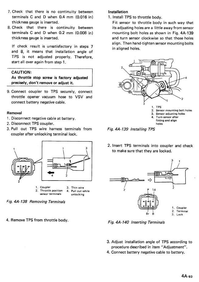
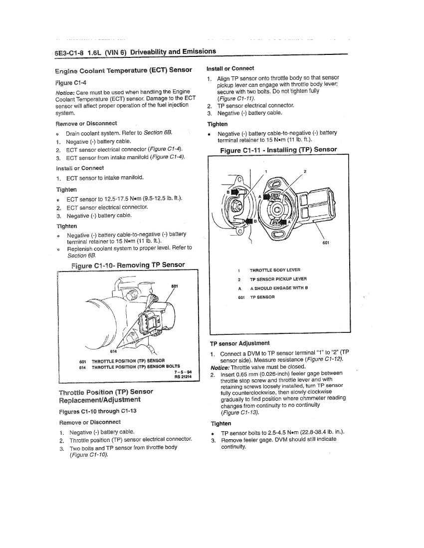
FSM TBI actual pages on calibration. THE REAL DEAL !
Never adjust the painted or capped off, throttle stop screw , for any reason. it is a factory calibration for minimum air supply {tiny}. (except 89/90 years)
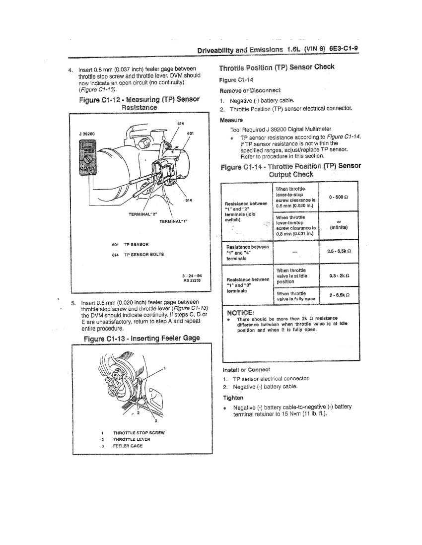
Below are the actual FSM pages for TPS calibration: TBI 1991 and UP.
8v Page1 with pin connections.
8v Page2 with feeler gauge spec.
End FSM 8v.
EARLY 1989 and 1990 TPS Calibration and idle speed
These 2 years, are very unique.
All steps here:
This is the 89/90 steps for TPS calibration and idle speed, these 2 years are unique. (<<<I Show the wrong TB in some photos) but does not matter.! What matters are the steps.
See other pre 1989/90 uniquenesses here.
Photo #2 (early TBI) this is a real photo. (note no water pipes to the ISC on the left)
END all 8V TBI testing and Calibration.
16 valve G16B 1.6L MPI TPS fast checks then CALIBRATION procedures. The 3 video tests (mp4)
The 1996 to 1998 real FSM calibration procedures for TPS is Here and Here.
See hopeless.
Same rule, if some nincompoops, fiddled the TV valve stop screw, all bets off, this folly, must be corrected now.
The tests are really the same as the 8v
- Different pin numbers
- No dash pot. The 16v uses software for a Dashpot function.
- Different feeler gauges sizes
The TPS must not be bad.
Factory TPS calibration procedure for the 16valve MPI 92-98 Sidekick or Trackers. <click with comments.
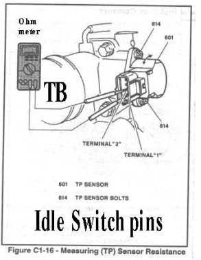
The 16v TPS has no pig tail connector like 8v has, but has 4 pins, and pin 1 is on the bottom. as seen below.
below is terminal 1 to 3 test for the POT test. Suzuki calls this the TP pin, but is known today at Throttle Angle.
As you can see pin 1 is the bottom pin. (ground)
On car pin one is 5vdc key on and pin 1 is ground.
The pin 3 throttle angle varies from about 1v to 4v (non critical) but must be linear in action (foot throttle) and not glitch. (the volts must not glitch running or ohms when tested)
Pin 2 is the idle switch. is 5vdc when not at idle and near 0v when at idle.
Pin 2 must be below 500ohms key off connector off. 300 or less is a better goal as most do near 50 ohms pin 1 to pin 2.
All pins on all MPI TPS look like this and rules and wire colors !
The idle switch must be closed and near 0v running or the timing freeze and many things will fail.
The below graphic is for the OHMS test, but in fact this same drawing shows you, what pins to test for the live voltage tests. (use the 8v rules for these test above)
Graphic #2 This is not calibration yet, this is just checking throttle angle.
This Graphic is just to see where pin 1 is and all 4. 1,2,3,4, bottom up.
 16 valve MPI only. all years. 92-98
The on car live, key on, voltage test is here. You must leave the connector connected,and us a back probe technique, to read the voltages.
Pin 1 Ground. Gray/ yellow 0 Volts.
Pin 2 Idle switch out Blue/white (0v when at idle 5v off idle ) Some GM books show pin 1 as 5v, this IS WRONG.
Pin 3 TPS TP pin wiper POT or TP throttle angle Gray wire output varies from .5v to about 3.5v idle to WOT.
Pin 4 +5vdc from ECU. Gray/red
All colors are harness colors. GM and SUZUKI may use different colors on wires, but pin 1 is always down.
FYI: TPS functions are all explained.
16V TPS Calibration method: (FSM steps expanded) See testing here.
“CAL steps) TV means Throttle valve inside the TB the Throttle body.
(Throttle Position Sensor, Switch) See above graphic 1, for pin assignments. See hopeless.
Before calibration, there must not be these gross errors:
- The TV valve must be closed 100% not carbon blocked
- The TV can have up to 3 cables and each must be adjusted to factory spec. slack 10mm (7/16″ inch) ( Up to 3 cables on A/T cars and cruise opted engines.)
- In all cases, if the TPS is not installed and indexed and preloaded correctly, to the TV end pins per FSM, all bets are off. (it will fail ! or even jam the throttle)
- The nincompoop errors corrected. (some joker fiddled the stop screw?) The correction is here. The fiddle Fix.
- The throttle crank (where cable end fit) must land on the throttle stop screw head.
The TPS mounts to the TB (throttle body) side and measures TV actions, and reports them to the ECU.
Adjusting the TPS switch is the ACT of Calibration.
The TPS is just a variable carbon resistor inside, no magic or electronics, just carbon.
Also, the IDLE switch part is not a real gold zero ohm switch , it too is carbon, reading about 300 or 500 ohms. It will never read 0 ohms. On a running engine the idle switch reads 0v. (if not ? it needs calibration or error 1 ,2,3 corrected above)
{ FSM is Factory Service Manual }
Pre-conditionals:
TPS not bad ,so test it first (using volts above live or resistance tests).
See chart above (table) for exact Go , NOGO and CAL feeler gauges.
Tools:
A set of feeler gauges. a $2 tool.
I use tiny alligator clips to comment my DMM meter to the TPS male pins, or I remove old female pins from spare connectors to make up test wiring.
Attach an Ohm meter (DVM set to ohms resistance starting on the 2k range “2000 ohms”) per instructions. (auto ranged meters, works ok too)
Begin the calibration. ( I will cover 92-98 1.6L 16valve MPI method here) A GO /NOGO method this is called. (factory methods)
- The Ignition Key is turned off,.
- TPS end Connector unplugged, do not force it. All conn. have lever locks, and Suzuki don’t sell connectors. (just harnesses, if lucky)
- On my 1996 the top of the TB has this huge black beauty plastic cover blocking all linkage,; remove that first,.
- Place or Insert ( a 0.026″ feeler gauge between the TV crank stop and stop screw head. (Removing the cable bracket seen below is a great idea. Just 2 nuts hold it)
- Loosen TPS side screws, so they are only slightly tight. See photo of off car CAL.
- Then rotate the TPS CCW, then rotate CW it until the TPS (pin1 and 2 ) just barely (at the threshold) go to Infinity on DMM ohms scale. (Counter clock wise = CCW)
- Tighten the TPS side mount screws.
- Remove Feeler gage, note the Ohm meter (Resistance meter) shows continuity (less than 300 ohms) (ECU expects less than 500 ) (do not expect zero ohms!)
- If the TPS screw mount slots bottom out, here the TV valve shaft is bent or the valve stop screws were VIOLATED, (see my crude solutions here)
- Insert 0.037″ feeler gage here (stacking the gages works great) NOGO step
- The ohm meter now reads Infinity. ( not 300 or 50 ohms or less,or some other value , but true infinity)
- Now insert the 0.020 inch feeler gauge. and the reading must show 300 ohms or less. GO step ( I get 50 ohms , usually, do not expect 0 ohms)
- Tighten all TPS screws (a double check) and put back its connector.
- if any of these steps fail. repeat them all. (if it wont calibrate the TPS is bad or mounted wrong or the TV is not closed 100% or someone bent the TV shaft or the TPS is not indexed to the body right.)
To be sure,must guys just set it to .026″ drive around the block and all is well.
This method guarantees some tiny fractions of inches ( of over/under-travel.) See chart on top of this page.
If this calibration is done wrong the following may (will) result.
- A dead ISC, or one that is active when you accelerate say to 1000 RPM,
- The engine will never idle or will idle out (DIE) at stop signs, etc. Or RACE at high speed, the IDLE will NOT regulate. and Fast idle commands(ECU) will never happen. (A/C fast idle)
- If not closed this idle switch, at idle the timing freeze jumper then fails to freeze timing , as desired, for static spark timing, procedures.
- if set (closed switch) to far into the TPS range, then the car , will have TIP-IN bogging. Too late TPS idle switch opening. The ISC will fight your right foot in a very strange way…
- My 96 Suzuki will surge above 1500 if the switch stays closed too far into cruise range.
- When you cut the throttle and the TPS fails to close, the EGR cut will fail, as will the Dash-Pot effect, anti neck snapping feature , of cut fuel mode.
- The ECU now throws, DTC errors for the TPS.
- There are many features and function in the ECU that trigger off this TPS switch, most or all will malfunction.
Real TB 16v: 1996 actual.
PHOTO 3: 92-98 look same.
Look carefully the cable has 10mm slack , it must. If you also look carefully the TV throttle stop screw is blocked from anyone touching it !!! “adjustments don’t (factory set) (the bracket does come off easy)
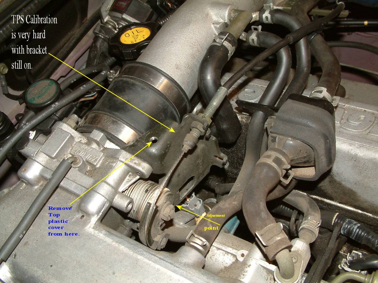
Below is Throttle body shown up side down, setting the TPS the easy way, it’s near impossible to set on car, with the above bracket in place. ( 2 nuts hold the bracket on, only)
The 16v Calibration point below: photo 4 is just and observation it is not a spec. I set the bore/TV gap (if monkeyed) (see my crude solutions here)
Never touch this screw below, the feeler is the Calibration tool . Go/NoGo and Calibrate sizes.
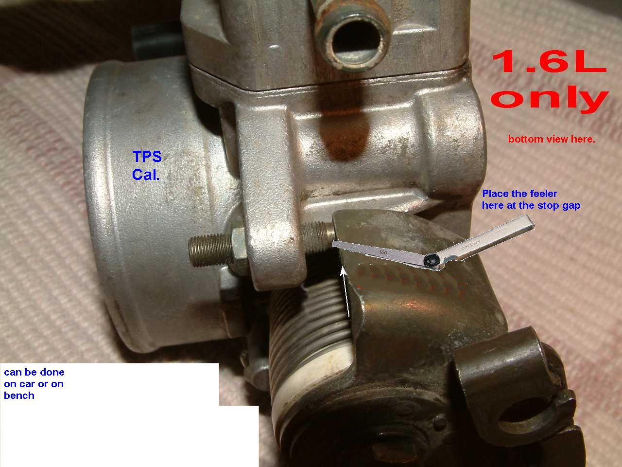
The TV bore is so closed, that it will not pass water, but is closed 99.9% and not 100.00% so the fly plate can not JAM. (or cause bore wear) Suzuki has NO SPEC. ON THIS at all !
Other car makers do spec. this gap and that is what I use for guide lines getting this correct. Ford tired having no screw and TVs jammed up. Way to go Ford.
For sure BENCH setting is super easy, and works best do to , you see carbon blockage at TV/ Bore , and fix that.
If the screw was MONKEYED and you fix that first and off car the throttle cable can’t interfere with the calibration.
Off car, you see the plate is not closed or is full of gunk blocking it open. (common on high mileage cars)
end calib. See how to fix the folly of finding that the TV valve is not 100% closed and some one messed with that screw above.
TESTING the 16V TPS.
THE OHMS test. Unplugged (not connected, testing) The 3 video tests (mp4)
(I recommend testing it before calibrating the sensor )
Doing the calibration is best done on th work bench. (but removing the left steel cable bracket does help on car calibrations)
The TPS can fail this way:
The Throttle Position pin , or TP
The TP pin, A.K.A. POT wiper pin or throttle angle pin : (Cold circuity test)
(POT side is never calibrated , only the switch side is calibrated on any of the 1.6L)
(The Throttle angle pin, allows fast acceleration rich mode “power enhancement” and causes WOT (wide open throttle mode) and causes Unflood mode at crank time. And cut fuel mode.
Key off:
Connector unplugged at the TPS 16v: (it has connector locks, be careful we cant buy new ones)
DMM/DVM: meter set to 20k Ohm range: See Figure 2 above for pin locations.
The pot side of this TP pin 1(bottom) and pin 3 , varies from very low ohms (typ. 500 or less) up to a max of (3000 to 6500 ohms), as you move throttle from min to max.
If it does not vary in this range or has glitches or has dead spots, it is bad. A $250+ Suzuki part. (all makers of this part, have rip off prices, it’s no Toyota, so they can do that)
It doesn’t have to be accurate , just consistent and linear. !! Again, this side (angle) , is never calibrated. !
The idle switch must close at idle. (0 volts connected on a running engine at idle (hot))
See calibration for more details.
DOA: Show and tell: (when things go wrong, never hit your TPS, oops , damaged , I bought a spare like this.! )
The Below internals of my TPS, are cracked, car will never idle. Look close and see cracks.
DO not open the TPS like I DID Below !, this is a destructive examination ! HACKED OPEN! shows cracks , that can happen.
This TPS was stuck in UNFLOOD mode, car will never start. due to fuel cut at cranking time.
Click to zoom image. Figure 3:
This damage happened during and engine removal. IT GOT HIT !
It also shows you how the carbon works, the Gold wiper device is missing here.
This shows you why the switch part never hits 0 ohms, like a real switch, that is because this one is Carbon, not gold contacts.
Photo 5, do not attempt to do this. This is just to show the guts and how it can crack inside.
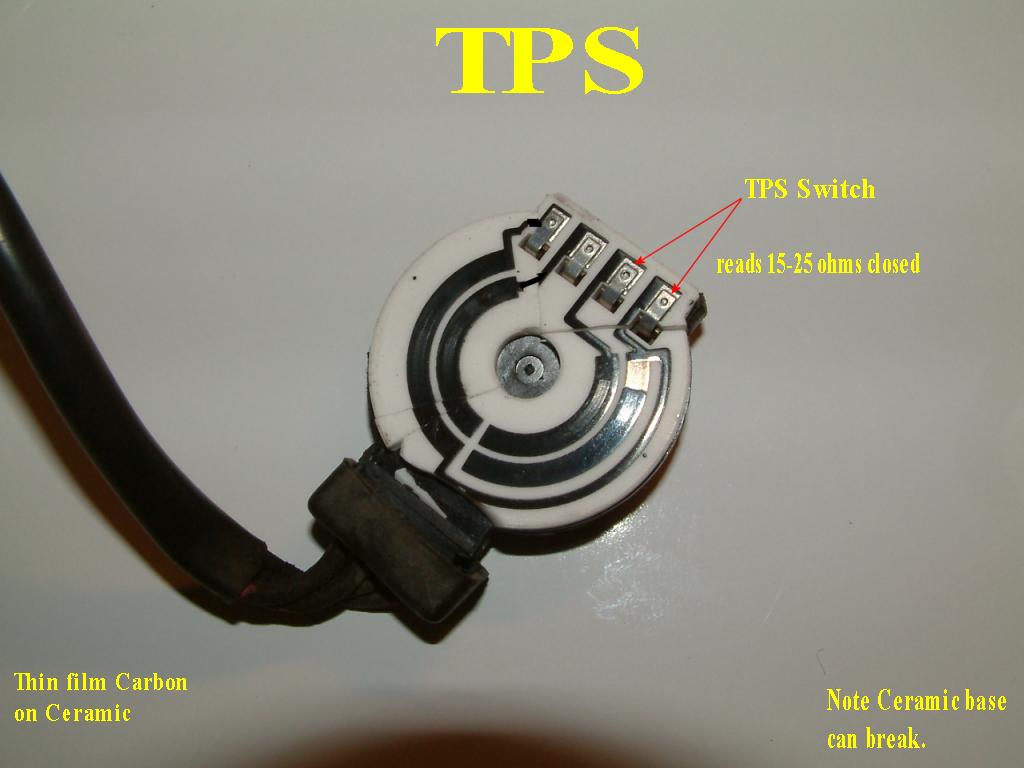 My broken TPS, internals, hacked open
Seeing the ceramic substrate and the carbon thin films , is very visual and clear what is going on inside.
This photo clearly shows the 2 devices inside, the unit. a switch (right) and the POT. on the left.
the 2 (not shown) wipers short the inner and outer rings as they wipe.
The TPS is infamous to go intermittent first, then fail hard.
IF the TP pin has glitches as you accelerate? Then the ECU causes a hesitation when you demand power. This is caused by worn carbon on the above rings, end of life.
1.8L DOHC J18 engine (or 2.0L J20) Sport Suzuki TPS calibration on the throttle body. “TB”.
(1.8L and bigger motors. have no SWITCH at all now, one just sets the volts and you are done) {0.5v at HOT idle , key on)
- All TB cables are 10mm loose. per the FSM, normal slack, they are never set tight (very dangerous if set tight. The same for cruise option cable. and kick down cables
- The TPS is indexed correctly , that is, inside below the TPS are index pins they must be aligned, and for sure not jamming the throttle open. Remove it and check it.
- Make sure the throttle fully drops the butterfly and end crank against the stops, there is a screw there, that bottoms out, do not ever touch that screw.
- Key on, no need to start engine.
- Connect the DMM volt meter to ground , TB casing, and the red lead to the TP pin, via back probing of the TPS connector .
- loosen the TPS screws until just a tad loose.
- Adjust the TPS to 0.5v that is 1/2 volt, exactly
- Lock down those TPS side screws. You are done. Now the ECU will enter idle mode and activate the ISC system.
(Which pin is TP ?. well, one is ground , one is 5v, and TP is low volts) It’s the gray wire, with no stripe.)
See Full PDF (8pages) factory CALIBRATION.
J18 idle speeds out of control are covered here.
Unique changes to J18 engine (evolution) are seen here.
METER MADNESS:
Volt meter, Ohm meter (resistance) or DMM. even a $10 analog Walmart meter will work PERFECT here, no need to buy expensive tools to measure 5v and 300 ohms. Not at all.
How to use the DMM is here.
General Information on TPS: (and facts and myth debunking)
There are 2 sections in this device, the top section is the Potentiometer (POT) or as some call it a variable resistor. A,B and D. (1,2,3,4 on 16v)
So there are 2 tests and only 1 calibration.
Side one is called the IDLE SWITCH , the other side, is the TP (throttle position side or Throttle Angle), This side form a basic Potentiometer, (POT) or variable resistor.
The calibration is only conducted with the SWITCH SIDE. C and D Pins. (8v example)
Failure of Idle switch:
If the switch fails , the car will NEVER idle correctly ( it will vary with load on the engine)
This switch is not a gold contact switch, it’s just a carbon chunk, It has only 2 readings. less than 500 ohm and infinity. Never expect zero when closed ,like most switches.
The Fast idle control features will fail, the Cut fuel and EGR may fail. The ISC will be dead !
The late to open idle switch, will case Tip-in fuel mixing problems. Tip-in as in your right foot tips in the throttle and engine hesitates a bit.
The POT side TP SIDE:
Myth 1: No, the TP side does not set fuel injection rates, that is, the ohms (voltage) does not get scaled directly to injection quantity. But does in LIMPHOME.
The TP does get watched by the ECU, for rate of TV action, you move the throttle fast and the ECU sees that and goes to ENRICH mode, until the MAF/MAP catches up.
If you have a throttle hesitation problem then do the range test or the POT and ohm meter (resistance meter) test.
If POT TP wiper pin B or 3(16v) (reads above +3.75vdc ,when trying to start the car, the car will NEVER start.
The rule for WOT is “About” 75% and above Throttle angle is Unflood mode. The TP usually has 4vdc output at 100% throttle. can be more..
Un-flood mode. I mention this, because the ground can be broken to the TPS at pin D (p4-16v)and the car will never start. Unflood mode forever. CUTFUEL cranking.
The POT side, has 2 rules (besides that the actual accuracy is very crude, some pots are 3k and some are 6k ohms, a crude device.
1: The end to end ohms on your POT must be steady at all times. if it reads 4k is must, be so, at all times (that is how your’s is and works)
2: As you measure the Pot wiper pin, to the other end ground pin, say D or (16v pin 1) the TP pin must vary from below 2k ohms to max what ever you read in line above.
The key here, is that the wiper pin must NEVER jump open (infinity) as you move the throttle.
This is very common , this failure of the TPS. after 100k miles many TPS can fail on any car, and depends, on utility, be that, city ,highway or mix, when that happens.
It it rare for any TPS to last the life of the engine. (about 300k)
This page is only complex because of the 10 years covered and 2 engines and evolutions of the same.
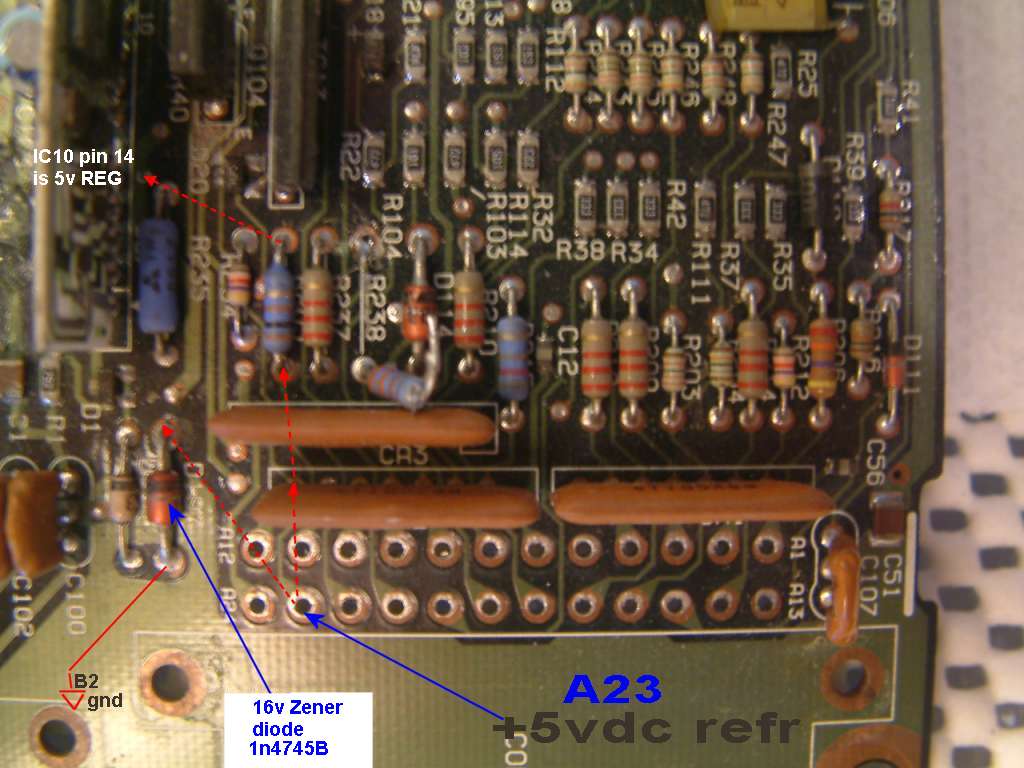
Never ground out the +5vcd refr. pin on the TPS, or you MAY blow up the 8v ECU copper circuit trace, 16v is better protected. (nor pray tell short this to 12vdc. ouch) Never hot wire any output pins on any ECU.
Never hot wire any ECU output pins, or you will damage these simple ECU’s . (hot to battery Plus or ground) <<< never break this law !
Never hot wire or ground out the ECU +5vdc(Ref) pin. (if 5vdc is wrong, the TPS will not work. spec is. 4.75 to 5.25v and is a power supply from ECU to sensors.
Never hot wire the main relay or fuel pump relay or blow the ECU driver transistors to H3LL.
Never hot wire injectors or VSV solenoid valves with ECU hooked up.. or Boom “you let the smoke out !”
TPS FAILS: (TPS , it’s wires. or bad ECU +5vdc ref power source) (the DTC code # change for 96+ but the words and reasons don’t)
Previous owner removed it and put it back and now its not calibrated or did the calibration guessing or with wrong feeler gauges?
The sensors all eventually wear out and the throttle angle pins starts glitching or has dead spots.
TPS switch open, LIMPHOME IS IN EFFECT car starts, no idle controls, at all , ISC will be dead. DTC 44 , and 45 ( 45 is stuck at ground , very rare this , is a harness short)
Other pins open will throw over voltage DTCs for TPS. (or under of 5v is missing)
Open ground pin, the TPS goes to 5v and ECU may give warning and engine may not start and DTC code 21
( over 3.5vdc on the TP pin can cause UNFLOOD mode and all injections stop, depends on ECU year and its software)
(22 is stuck low)
The TP pin pin can do that (DTC #22) and is a bad TPS. or open 5v wire (like 5vdc is dead on the 5v pin of TPS, 5vdc gone is bad ECU )
The TPS can crack inside (see photo just above) or wear out inside and give totally random symptoms.
The ECU has a tendency to not see TP glitches (denouncing logic) and will cause hesitations, when advancing the throttle. (the ECU can’t tell the difference from a glitching TPS or a driver with a wild right foot)
If the TPS errors are bad enough (with DTC’s to match) and constant, the ECU may go, to limphome mode and car does start.(due to flooding) (it the ECU, mimics the bad TPS and runs VERY BADLY)
Keep in mind a failing TPS may send voltages to the ECU that the ECU likes and believes and Unflood mode gets activated. (silently; no DTC) (if the angle is at say 4v , the ECU thinks that is not an error , just the driver doing UNflood mode per operators guide)
One guy mis-indexed the TPS prongs to the matching prongs in the TB, and he got Unflood mode. (4vdc on TP pin) all injections cut.
Not properly indexing the TV shaft pins to the TPS can cause TPS to stick throttle open. (engine races at idle) Say you look in the throttle bore and the TV is not closed (with dashpot retracted on TBI). BINGO !
WOT is about 3.5v or more at the TP pin , and cuts all fuel , cranking… (it’s a feature set on all EFI 1989 to present)
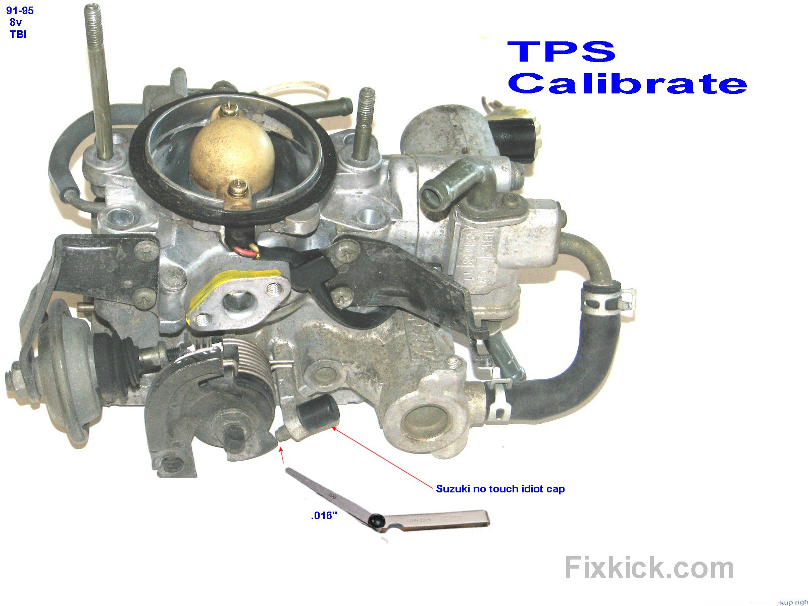
The 8V TBI below: TPS calibration point. TPS is located on the other side of the throttle shaft. The Dash pot is on the lower left, clearly seen.
Photo 6: The idle stop screw must never be turned.
 f
f
The feeler gauge goes here above , to set the TPS calibration.
These errors can also cause the spark timing freeze jumper to fail, and timing jumps, when frozen by you and your jumper wire.
The TPS activates, idle controls, and allows the EGR to operate and many other things, so the idle switch must be calibrated or all this things fail.
The Nincompoop section , there are no limits to damage or people doing crazy things to cars, wrong parts, or damaging them. (my short list, lol)
Or bad luck, fate, or ?
PO = Previous Owners.
- Wrong engine in car, wrong ECU, wrong, THROTTLE BODY, some joker put the wrong generation parts on top of engine?
- The dash pot device on the TBI 8v must be retracted for all tests idle speed setting and calibration.
- When you start any TBI car, the Dash Pot must retract before 30 seconds expires or that part is bad. the Dash Pot VSV valve or the DP hose,etc.
- The TPS wires, are cut or worse cut and spliced on backwards. (corroded connectors after 20 years, no !) Causing DTC errors like mad.
- The TV was molested. The throttle valve adjuster screw was messed with , 1991 and newer cars. this is totally bad.
- The TPS was calibrated with the DP active. (DP = dashpot on rear of 8v TB) TB means Throttle Body.
- The TPS was calibrated, but not tested with all 3 feeler gages, 91’+
- The TPS was mounted wrong to TB side, and not indexing to the internal tabs , thus jamming the TV at idle and making TPS calibration , impossible.
- The wrong factory part number TPS was installed.
- The TPS acts oddly, because the ECU is in FAILSAFE/Backup mode, (TPS unplugged too, does that, besides others ( a dead MAP/MAF will cause the TPS to be the primary air meter… oops)
- The TPS, is dead because you have a A/T to M/T swaps or the reverse and done wrong, wired wrong or the wrong ECU used, for each.
- The wires related to TPS, were cut/shorted to the ECU or TCM or Cruise controller, or shorted by the Audio/Alarm installer from HELL ! “TPS WIRES” This other devices must not short out the throttle angle pin, ever.
- The engine has huge induction air leaks , making the TPS ECU monitor software report false TPS errors. (ECU sees, idle switch closed and RPM is a 4000 RPM, and low plenum vacuum..oops.?)
- The ECU +5Vref pin is stuck at 0v, making the TPS useless, and DTC codes thrown. (low TP voltage)
- PO removed the TV throttle valve plate (brass) and filed it or drilled holes in the TV plate (an abomination!) (seen this was done to solve low idle issues, a sure sign of desperation, and the poor guy never saw the idle bleed screw… sigh)
- None of the 3 throttle cables: 1-driver, 2-A/T kick down or 3-Cruise cables, interfering with the throttle valve. The FSM spec. is 10mm slack , (7/16 inch)!
- These 3 cables must not be set tight, with dash pot retracted on 8v TBI engine.
- A Missing Dashpot on G16a engine. (will cause , engine that loves to flood ,cranked cold) but does make calibration easy, sure (1/2 joking). (will not cause timing freeze to fail)
- Gunk under the throttle valve, in, under and around the butterfly plate to bore. (blocking it open)
- The TPS was calibrated using the wrong feeler gauges, as seen on many store, rag books or on line.
- The TPS was not set with the feeler gauge on the threshold of closure. It must not over or under travel.
- The TPS switch is not closed at idle, for any reasons.
- The TPS fails to open , at the correct moment the ECU will be very vary unhappy as the idle controls fight your right foot. at throttle tip-in (evil effects here)
- Not correcting DTC 21, 22, 44, 45 first. and others or the 1996+ equivalent codes. P0xx codes.
- Say the 1991 car has a 1989 actual engine, (or parts) and not 1991 . oops wrong TBI there for your ECU.
- DTC errors. The ECU is telling you there are TPS, TP or Idle switch errors. see above links? or is in FAILSAFE. Failsafe mode, kills idle controls.
- Engine idle controls dead, the RPM don’t hold at 800 plus or minus 50 RPM with all electrical accessories flipped on then off, (blower/defrost?) or on A/T Tranny shifting from park to drive?
- Engine idle speed hunts, this can be a lean engine or the ISC can not get idle to 800 RPM, if it can’t, for any reasons , it can and will HUNT, a.k.a: Surge.
- You tip-in the throttle gently at idle driving, and the engine fights you. (late idle switch opening? )Some call it a JUMP or hop, but is a very strange feeling. (PO guessed at above CALIB?)
- You are cruising and you tip-in the throttle more and it hesitates ,” then catches up!” This is a bad TPS TP signal. The TP “Angle” pin carbon section inside, is worn as all do , eventually)
The TPS on this car is tricky to calibrate (16v). The key to success is understanding the threshold issues during calibration.
The TPS idle switch must close every time you drop the throttle (to near 0v)
and
The TPS switch, must open at the “correct moment” or the ECU will be very confused ! This is why the feeler gauges are used.
The TPS usually can never causes stalling, the #1 cause of that bad act, is EGR stuck open. (but can if the ISC goes dead and other failures, prevent air flow to the engine or very weak fueling as this idle switch will shut down, the ISC)
There are many failures on the EFI system that can seem like a bad TPS and is not. (Fuel pressure wrong, timing belt slipped, EGR stuck open, leaking injectors,clogged injectors (full or partial))…
Exceptions: (to how the TPS is used)
One is a cold engine. (off topic )
How the TPS is used on a cold engine veries by car maker (ECU tuner), my whole pages covers only a hot running engine. 180ºF + coolant temperatures.
If the ECU is in failsafe mode due to a Dead MAF (MPI) or Dead (MAP) sensor , the ECU then uses the TPS to mimic this dead sensor, and now becomes the only (+ RPM) way to measure air flow. The word crude is an understatement here…
This mode of running is very rich fueling (and very crude) and the CAT converter will overheat. (even glowing cherry red)
DTC errors, 31, 32 ,33 or 34, or starting in 1996 DTC errors P0101, 102,or 103 (These errors trip failsafe)
DIY: crude way, ( super easy, super cheap , fast?)
Using “Walmart leather sewing needles” work great. (with alligator clips to hold them) “these can work great”
PRO GRADE.
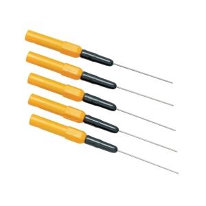 back probing pro needles , banana cables to needles. (for back probing or pin probes with no damage to the pins.)
As the name states, backprobing is the art of connecting to live circuits, at connectors still connected, past those rubber seals there…
Great for testing all sensors on the car.
Buzz words:
CCW = counter clock wise , CW , guess?
W.O.T = Wide Open Throttle. (over 75 % is WOT most cars)
TPS = Throttle Position sensor, or TP and Throttle Position , on newer cars 96+ it is called a Throttle angle sensor.
Pot. = for Potentiometer, or variable resistor. Pot for short !, This pot is just throttle angle. Nothing more. (varies from 1v to 4v as you move the throttle, typically)
TP pin is the Throttle angle pin (wiper) of the TPS, not the idle switch. An electronics guy, calls this the wiper pin, that is because it wipes the carbon, as it moves and picks off a new resistance, as it moves.
Glitching = This means that the voltage or resistance is not linear at the TP pin (throttle angle) seen here as glitching open .
The idle switch will be below 300 to 500 ohms or near 0 volts idling (lower ohms, is ok , higher not, when at idle) {mine reads 50 ohms }
TB = Throttle Body.
TV = throttle valve, that is the butterfly valve, dead center inside the TB ,the Throttle body.
PO = Previous owners, (mostly with no books or tools)
M/T = Manual transmission, A/T , yes, automatic (this is all ASE /SAE jargon.
ECU , engine controller unit (a.k.a. ECM or PCM)
TCM, transmission controller module (4 speed automatic)
STOICH: (means perfect fueling) that happens in Closed Loop mode of the ECU.
Gunk means that nasty junk below the Throttle valve, (butterfly valve) that is created by EGR gas cloud, smacking in to the PCV cloud. and forming a tar like substance.”GUNK”
TBI , the 8 valve engine with black top valve cover . Throttle body INJECTED with just 1 injector. (aka SPI ,er, single point injected, bla bla)
MPI, the 16valve engine with the words 16 valves embossed on top of valve cover, and is multipoint INJECTED (4 injectors)
Hi! Thats very very helpful! And very accurate, even i dont know english very well. I have a question: if my tps Is bad and i Need to replace, can I get another car’s tps? Such as Subaru or Grand Vitara? The original tps costs too much. Thank you from italy
no.
only the correct part works
sold easy at rockauto.com
this car like all new cars cars have tps autocal (learn) in the PCM. not this car.