And Trackers too:
A/T car can have 1 extra vacuum line to A/T 3sp and one extra throttle (TV detent) cable and one more if car has cruise option.(all at the intake manifold)
JARGON words used
What do the motor parts weigh? (if you have to ship them ?)
On both engines, just unbolt the exhaust manifold and tie it to the left and let it float there out of the way.
G16A, 8V It's easy to remove this intake. 8valve has black valve cover of steel. (no words on cover)
G16B 16v: Motor just unbolt and float the intake to the right side strut. (left facing engine) The 16v says on top 16 Valves cast in to the valve cover.
You may need to pull the top Intake manifold runners with 8 bolts. (98 year this is impossible , no bolts here) with Throttle body , sans cables.
On the 98 the to intake section, is not removable , remove the whole 98 intake manifold, first. (tedious, due to bolt access issues)
The reasons are, to get to the difficult to reach, fuel banjo bolt, at back of fuel RAIL and to gain easy access to all bolts.
DIY:
All directions here, are from the drivers perspective, seated in drivers seat. (LEFT is drivers seated perspective , LHD (left-hand-drive) SAE standards..
The below works and is effective, on any air conditioned car. see photo proof.> NO EVACUATION of A/C loop !
Disconnect the battery Negative lug first.
Next !, De-pressurize the fuel system
Safety step 1: Unscrew the gas cap 1 turn or expanding fuel will flood you garage , after step 16 happens. or remove the cap an put it on the dash top.
Never pull the head until the water pump is off, this fully drains the block , thus keeping antifreeze out of the engine crankcase (I the pump before the head !)
Trick one, pull head with intake stilled installed on 16v , you need to pull the front harness connector to fuel injectors. Located just below the front of fuel rail, see slide show.
G16B 16v:
The G16B HEAD can be pulled with induction fully in place, if you drop the "Y" under mount bracket under Intake manifold. < this brace is FRAME ATTACHED !
Trick two: pull the induction top runners 8 bolts, on 16v and gain access to the rear mounted rail fuel source banjo and harnesses and small hoses.
Non of this is above is complex on 8v. (all in plain view and easy to remove)
One liners: ( you use tape and mark all small hoses before pulling the motor , standard practices) "duct tape and a pen ? IAC-t for top"
Best is to get head totally free of all things, and then get access to the head bolts (the cam hides some of them) (really this is all you need to know besides coolant drained)
Please read the fuel warning here first.
Italic lines are options: ( park and float intake man., remove it as one, or removing it with head, I vote FLOAT IT and PARK IT)
You need to remove all belts, and all manifolds. (some leave the exhaust manifold attached with header dropped off, pulling head and exhaust manifold as one,)
Same with Intake, but is very hard to that with 16v removed with all manifold left on head. (but does make nice handles to do that....)
- Decide now, on whether to pull head with intake attached or not. I drop the Intake bolts (and exhaust) and them both out board with Bungee cords. FLOAT WAY!
- Disconnect battery Negative LUG FIRST !. and Positive. terminals , in that order! best is pull battery OUT.
- Relieve all fuel pressure, by running motor and pulling fuel pump relay. skip this if floating intake head on.
- Remove the INTAKE MAIN DUCT PIPES crossover, and if 16v the MAF. 8v has bolts hidden under a plastic cover.(right side)
- Drain RAD fluid , at bottom left is drain cock.
- Remove all water hoses connected to the head.
Look behind head for a hose and
under intake manifold, if removing head
with manifold.
- Disconnect all RADiator oil cooler hoses. ( I remove the RAD so I can work on the front of engine with full ease)
- First loosen the nuts on the end of the water pump FIRST, then
when belt is off , the fan will unbolt easy.
- Loosen all Alternator pivots and adjusters and then pivot alternator inward. (3points) The water pump pulley is now loose and free.
- Remove
the fan from the
W.Pump pulley . Remove all RAD shroud screws and remove the fan, shroud
as
one with fan, on these 2 items and RAD all together if necessary
(hand/arm sizes matter)
- Remove the Radiator ,with the shroud and fan by removing 2 Radiator bolts on the top sides. (protect the rad, using hard(card)board from A/C condenser screws tips doing damage here.)
- Remove all accessory belts shown here.
Power steering and A/C. Then the timing belt removed. The Timing belt page covers that.
- Short: Crank pulley off (small screws) cover off ,9
screws, timing belt
tensioner loosened, and belt falls off. Head is now free of
this cog belt. (this is cam timing, not just a belt)
- I REMOVE THE WATER PUMP NOW so
the Antifreeze (AF) in the block drains all the way out, at pump
cavity. You do not want "AF" to
get in the engine
oil system !
- There is a side block
drain plug, but is super hard to remove... most take torch heated...
- To float or not to float
(intake):
- I must say
unbolting
and floating
(option1) the intake manifold allows you to
leave many water hoses alone. Or Skip
to lines below
- Just tie the Intake to the side after unbolting it from head, if not doing this , remove all items connected to the intake manifold. Per below.
- At fire wall ,
right, remove both cab heater core hoses at
fire wall ( I cut them , or you risk core tube damage! WARNING)
On 16v, you must
remove a hose behind the head. This step is why I park the INTAKE
manifold and do not remove it or do not remove it a AS ONE with head.
That heater core is very weak. protect it.
- If removing intake
manifold totally off car?, remove all vacuum lines
hoses, cables,
wires to it. tag them all.
- Remove the grounds at manifold right rear (96+) or many of these grounds mentioned here, on older cars (obvious)..
- Remove all wires and hoses , lines from the HEAD . Tag them and mark them.
- Remove
the whole Intake top 16v plenum box with 8 bolts (1998 you
can't). On the 98 remove the throttle body or at least its
cables. to free of the intake manifold.
- Remove EVAP canister and disconnect its hoses , lower right side of fender. this gains access to the 16v intake bottom "Y" brace. (this brace locks intake to the frame mount)
- Remove 16v intake manifold BOTTOM "Y" brace (right) 3 bolts. No need to remove injector harness or pull its connector if manifold is left in place floating.
- Remove all bolts on the
intake manifold and tie it back to the right side of engine BAY (my option1)
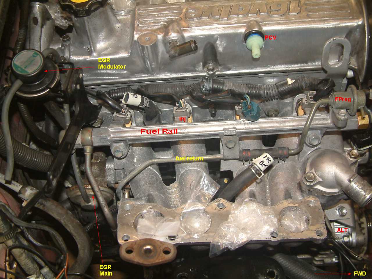
- Remove fuel return line 8v at fuel pump reguator right nipple (at TB) or (2 simple screw clamps) above center of fuel rail 8v. Skip this on option 1. Float Intake.
- Remove the fuel line behind the 8v TB (throttle body) or at the rear of the rail , the banjo fitting. do not lose order or location of 2 copper seal washers. !!
- Wrap the fuel lines
in plastic warp and with a rubber bands.
- Disconnect the EXhaust manifold and float it and tie it to
the
left
finder with bungee cords. (saves dealing with rusty header bolts)
- Disconnect the 3 main
engine electric
connectors , on
16v there is front
injector harness plug. unplug it. Leave the Intake harness
attached to the injectors.
- The Intake is now floating to the right of the head., most things are untouched on that assembly, if you follow my option 1 floating method .
- Remove
the valve cover , now. (park wires are off on 16v now)
- I pull the distributor, so I don't bump & damage it pulling head off. Put crank at TDC 0 degree mark, and rotor to #1 firing wire first.... if you do this. It needs to be off for head work anyway.
- Head bolt access:
- Remove the cam COG for head
bolt access on 16v engines. , by locking
the COG or CAM see how here.
- Remove the 16v cam caps ,
in
the proper staged steps shown here, in the Torque page..
- Remove the CAM. (8v has no caps, it just pulls out )
Removing the cam (now) is required to get to some bolts on the 16v
- The rocker rails need not be touched now,, head off car, but later sure and are impossible to pull on some G16 motors , head still on block.
- Remove the now exposed head bolts by using the same torque page head sequence,, stage the bolts down (less) 10ft/lbs at a time , if you can.
- The head is free. Lift it out. (do not attempt to
bump head side to side or front to rear, it has large locking pins,only
bump it up to free it.) Do no lose those pins, or cam belt will drift
later.(alignment wrong)
- Remove all parts on the head ,except the valves, and the 0.050 oil gallery orifice in the front left corner of the head. (never run with out it and never fail to make it 100% clean and clear)
- Clean and check the deck of the block for
warpage using the steel ruler , ruler cross over method with feeler
gauges.
the FSM has this test. In chapter 6 (generic spec. is 0.001" per
foot of head. (.002 is max in most cases)
- Send
head to machine shop for full pressure test, and full inspection.
(warpage , cracks, blown freeze plugs, and burned valves and if head
needs to be heated and relaxed from overheat damage.)
- Reverse the above process, with new head and watch for the pit falls.
- Install the water pump and Tbelt. and set lash.
- Time the distributor last.
- Fill and burp the 50% antifreeze coolant.
Pit falls: (see my torque page, with GM's errors removed/corrected )
Not using a FELPRO head gasket. Do not use no name china parts in the engine. Napa auto carries, Felpro (a top brand)
Losing the head to block guide pins, on the 2 corners , means the head will be canted, and the timing belt will never run straight and true ever. (causing it the hit things and shred)
Not putting the head gasket side that says this side up., "UP" is marked on the Felpro set, If you fail this step the head and cam burn up from lack of oil pressure.
Not checking top end oiling on first start (Valve cover off)
Consider using new head bolts. ( 8v are easy to find, but 16v not so, Suzuki does sell them all and are different for different years on G16)
The head bolts are not TTY (not torque to yield types) they are reusable of not too old, how old is too old, my guess is 10 years? or at first valve job.
Reading the GM FSM and believing the 89 FOOT/lb statements on cam caps, no, that is wrong, See my torque page corrections, see Suzuki states. 89 Inch pounds.
Not following the head bolt and Cam cap torque staging rules or REMOVAL and installation. see Torque page above for that.
Not checking the head front left corner , oil feed orifice fitting for clogs. it is 0.050" in diameter, less is FAIL , you will burn up the cam if this path is blocked.
Make sure the head galleries and orifice path are clear end to end , for perfect top end oiling.
Not checking block deck for warpage see FSM ( a machinist steel ruler ,run a X crossing head, and no more that .001" warpage per foot is a standard.)
Not checking head for warpage. see FSM. (same machinist tool and ways)
Don't Clean the head with metal brushes. (ok for plastic brushes and plastic scrapers and jet wash it or use paint thinner .)
Do not mix FOOT POUNDS with inch pounds, in the torque tables, no 6mm bolt can stand over 8 foot/pounds! (100 inch lbs is max). (Chilton's/Haynes, and GM books (96) get this all wrong.
Not using the torque wrench at every step on the head !
Machine shop rule:
Not heat relaxing any aluminum head , after it is warped, then last milling it, not out of order. Relax then Mill, or "shave" All aluminum head builders know this. ask them.
Installing new head:
Not setting lash by the book and checking 2 times, the last time with a 1,3,4,2 firing order walk through, watching the cam action, and lash gaps. Each valve must be loose(gap) when firing its cylinder.
Not setting the cam timing at #4 firing.
Not setting the distributor firing at #1
The Cam COG wheel:
Never Use "I" marks (keys and timing marks) on any G16B engine 16v. CAM COG wheel, USE ONLY the "E" marks for the key and for the E marked edge timing mark on the rim.
On 8v the correct mark is 60A on the spoke. Never use the 80C mark here.
Important things to replace at this point.
All new hoses and accessory belts.
A new water pump. (why burn up a new head?)
New Distributor o-rings (infamous common leak points) (one on housing ,other on Distributor shaft) [ must be re-timed ]
A new timing belt , is needed, never re-use them , over 10k miles old. Use a full GATES belt kits !
TSB, read them and do them.
Torque front crank 17mm bolt to 94 ft/lbs ( use vise grips at fly wheel or make a simple metal locker all this is covered on my Tbelt pages)
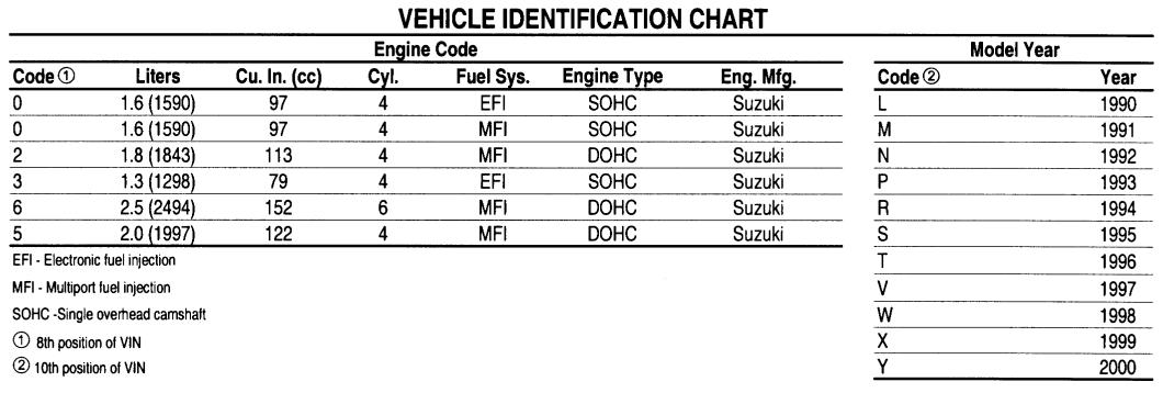
Get serial number off left side rear flange now, write it down, (check letter code for engine year )
This can be handy later, when buying parts.
New RAD fluid. RAD = Radiator for short. Coolant, antifreeze fresh and new.
Motor cleaner.
Nitrile gloves?
Head gasket. Felpro makes the best, bar none.... costs more, but is more...
Tools: STANDARD METRIC Shop tools /spanners , and 3/8" and 1/2" DRIVE metric sockets sets (there are no SAE imperial sized "inches" parts on car)
1/2" impact wrench helps for the the most stubborn large bolts. (head bolts , sure)
I needed a 1/2" drive Allen socket for my 16v head bolts ,that are ALLEN hex.
Both a 200 inch/lb and 200 Ft/lb torque wrench.
at the least.
A way to lock the flywheel or crank shaft (5sp use 5th gear and hard set brakes, CCW the bolt and hit breaker bar with a hammer or use IMPACT GUN,CCW)
Cam Cog lockers: (to get the nut off. CCW)
The G16B : The valve cover shouts "16 valves" casted into the top of cover.
(16v has no lock pin hole, seen below, on the 16v we have just behind the cog wheel, on head front a large 10mm tool.
Use a large ALLEN 10mm hex key and lock the cog to the front head gallery plug. CCW turn the cam cog bolt when locked. CCW means counter clock wise..
(I have 3/8 socket drive Allen key kit, so I used it 10mm bit and one 3/8" ratchet extension, to lock my cog.)
( some folks just use a Giant screw driver, stuffed in the COG) (be creative! try not to do damage.)
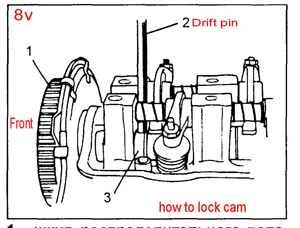
The G16A (8v) : Black steel valve cover. ONLY 8v!
Below by using the 8v cam lock hole on top with a drift pin (FSM) CCW the cam bolt. CCW , means counter clock-wise, turn the RHT BOLT CCW. (right hand treaded bolts,etc, are righty-tighty-lefty-loosey)
As you can see there is a hole in the cam shaft at #3 below. (8v only heads) The 16v has no such feature. The above head hex plug is used for locking 16v code wheel spokes, easy on 16v heads.
The Factory service manuals are online and free, and cover both engines.
The 16v (all) are covered here. Much better.
http://www.acksfaq.com/trackerfsm.htm
The 8v engine on the Samurai G13 is the same as G16A mostly, and is fully covered in Volume 1, chapter 3 here.
The sammy book shows how to lock the cam.
I'd not use Sammi, 50 ft..lbs on the crank cog nut, but use Sidekick 94 foot/lbs.
rev 4. 7-27-2011 , 6-26-2015, minor edits