Suzuki Sidekicks & Geo Trackers, only 1992 to 1998. 16 valve or the Tracker VIN code “6”
See the full distributor installation steps are here, if it was removed from the HEAD:
If your motor is G16A, or 8 valves? Then, go back one page to find the 8v procedure.
The page is long, because of all the was ways to mess up or if distributor was removed.
- Not just a simple easy fine tuning of timing. (see fast track below)
- Engine was totally dismantled or head was pulled? See long play way (21 steps)
- Crazy PO did some horrible errors. He pulled the Dizzy and put it back all wrong? Truly and endless list is here. PO = Previous Owners. See fast plant here.
- Cam belt was set wrong (oh, so many ways)?
- And all these Assumptions and pitfalls.
- The freeze jumper can fail, sure.
A Related topic, on LOST TDC, the fiddling about finding TDC 101.
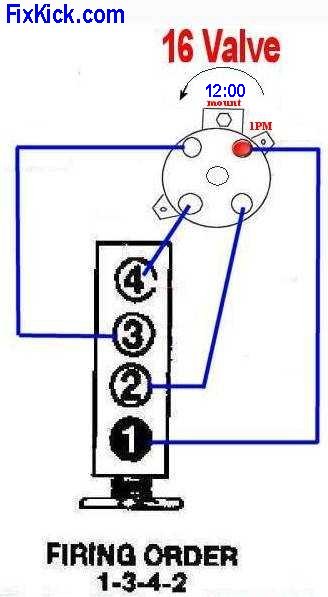
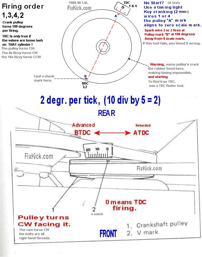
The Distributor (dizzy) rotor needs to be at 1pm at TDC.
The firing order is 1,3,4,2 CCW dizzy rotation it is, unlike 8v rotation. (and not like lies in most books) Counter Clock Wise it is.
Please time the cam using #4 marks.
Please time the distributor using #1 marks. I will not cover, timing the distributor to #4 nor the funny firing order 4,2,1,3 CCW.
Fast track, to checking or setting timing for spark, no mad previous owners, no slipped timing belts, (we do this, after every tune up, a fast check)
Assumptions here?
A fast fine adjustment list. (assumes crank pulley is clean and the timing belt cover scale is clean too.)
All accessories OFF, (no head lights, no A/C , no blower, no radios or amps, no rear defrost; only engine running, NOTHING ELSE)
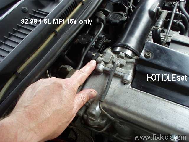
1: Hot motor (180f degrees minimum) running at proper idle speed.
2: Connect an ignition timing Strobe light to the #1 spark HV lead. (mid HV wire span is best)
3: Idle at 800 RPM (if not set it now) (TB idle bleed screw)
4: Set the Freeze jumper. (paper clip) conn. just in front of battery or near right front head light 1996+, Early Suzuki uses 4 pin DLC and 6, I’ve no idea what you have now.
At these Jumper pins 4 to 5 6pin DLC, or C to D on 4pin DLC. as your case my be.
If the freeze fails read this. (called timing bounce)
Check timing?, now at 800 RPM (+/- 50 rpm) per below:
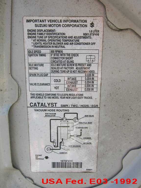
5: Point the Strobe at the timing scale see it at, or adjust it to, 5 Degree’s Before TDC (left side of zero scale mark) see under hood (“sticker” for factory spec on timing.
if just tad off (1deg?) adjust distributor base, if way off (a mad PO?) the timing belt has slipped, if true, do not touch distributor and do the cam belt first.
Hint, that hood sticker timing is different in different countries, our G16B uses 5°BTDC (fed) and 8°BTDC in CALIFORNIA. So why not read your hood sticker first?
Loosen the distributor base bolt and set the timing to the left of 0, advanced per YOUR sticker spec.
If the timing bounces, that is wrong, with the freeze jumper in place , there are 9 causes for that failure.
The 60k tune up, schedule states when to change the Cam belt, avoid skipping this service point and avoid being stranded.
If discovered “like magic” ignition timing is way off?, do the Tbelt sneak-a-peek check.
if spark timing is off and he cam belt is timed right then do the full dizzy timing procedure, someone hacked up your timing,.
This pages assumes you know how to use a strobe type ignition timing light, and that you know , the Dizzy spins Counter clock wise and the crank spins Clock wise (looking at pulley) (non believer? crank and look, behold!)
And that the marks, are clear.
Myths:
The 16v dizzy turns Clockwise, WRONG !, Most GM and Auto store book (rags) show this and is dead WRONG.
Many (most) books show the dizzy turning the wrong way, they lied. it turns CCW, watch the rotor cranking.
All Suzuki books, in print get this CORRECT.
SPEC:
Here are the timing specifications page based on your options and year or in California cars.
FACT: The Firing order, is 1,3,4,2 (CCW) ! #1 spark plug is the front of the car, Do no listen to myths or store bought RAGS.
The store bought books, try to cover 10 years, and 3 engine and mix up all the facts in a toxic soup. this page covers only the 16v .
The 8v Dizzy spins opposite to any 16v. That is their failing.
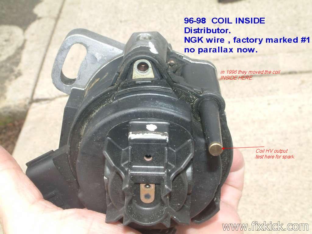
In 1996 the engine got a new Dizzy (spark coil inside) and a new crank sensor. (the later makes spark way more accurate)
Rule 1: Always replace the spark plug wires. 1 at a time.
This page is long , due to all the ways, to mess up, in reality, it only takes 5 min to do timing. (point strobe ,twist dizzy, lock it down)
Prerequisites:
The Crank shaft to cam timing is first , never last.
IF your cam timing belt slipped , snapped or stripped (they do just after 60k miles) or the keys sheared, then you must correct that first.
or ?
If your car runs pretty good, then jump to the FINE TUNE procedure.
There are 2 timing procedures. Coarse, sometimes called Static and then the fine tuned dynamic method.
The worse case method is , install the Distributor physically, and clamp it down using the coarse section below.
The coarse adjustment will be about 5 degrees ± accurate when done , and the car will start and run fine.
Later, you get a timing light and set the dynamic timing exactly.
Preliminary step:
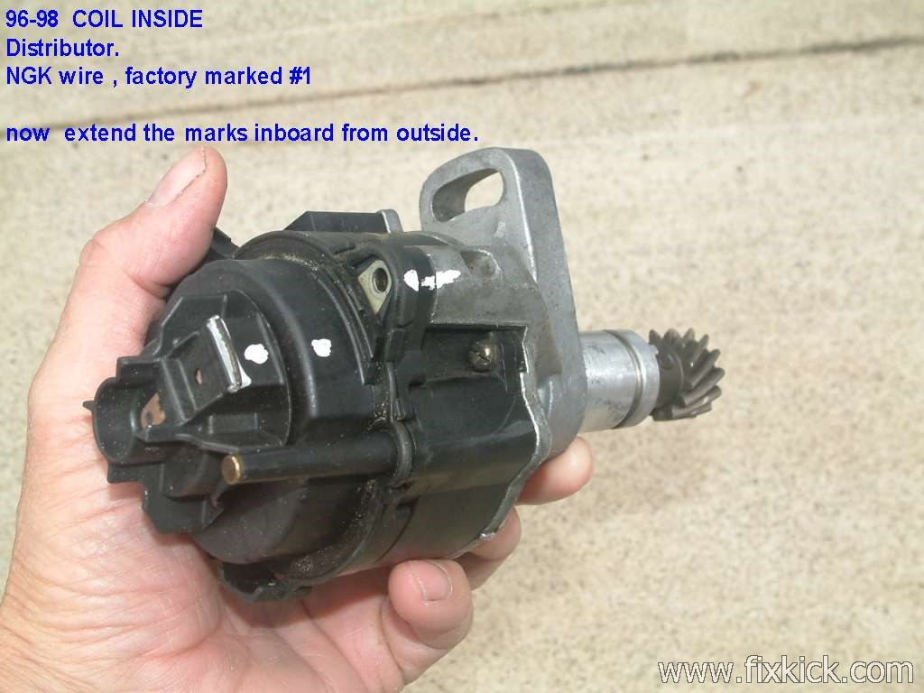
Attach the Cap to the Distributor body. look at the mount clamp hole on the body and position it to 12pm, then notice the first cap tower is at 1PM .
Put a mark on the cap in line with this position,down to the aluminum body and not mark the body.
The Distributor body now has a #1 mark. This can be done distributor on the car or off the car; it don’t matter at all.
The coarse adjustment: ( the adjustment done ,before the final final fine timing procedure.) We do this after Dizzy or head removal.
Also Know as STATIC timing adjustment:
Coarse is by hand and eyeball, dynamic is with a strobe light.
Optional step:
Consider replacing both the Distributor O-Rings on all high mileage Kicks, before doing this procedure, using Silicone grease. ( or leaks will happen)
The Main Housing to the Head O-ring , loves , to crack and then leak oil all over the back of the engine and down to the exhaust pipe.
WARNING:
If you are reading this, to find out how to time your Distributor and the previous owner, set the timing with the Distributor gears set to a non- standard position, and you do not wish to start from scratch , per below then , you must put the crank to TDC #1 firing and then pull the cap and write down where this last person timed your engine. WHERE IS #1 wire? mark this point on the Distributor body.
If you do not do this, you will never get the engine to run, if you mix up the HV spark wires.
If you do not heed this advice above, then you have only 2 choices, discover what this person did?, or follow my procedure below.
My procedure below is the OEM FSM method. (by the book). Please use this method.
There are 4 high voltage wires, you can in fact time the engine 4 different ways, but please do it the correct OEM way.
New or replacing the HV spark wires? Replace them one at time. (or mark the cap first) if not ?, you will have pain.
A running engine:
If you are just replacing cap or wires , then just swap one wire at a time or mark every cap port and each wire with a tag.
1 , 2, 3, … Done !
Best is marking everything, for most Distributor work, on a running motor and pre tear down!
FINDING #1 TDC?:
Set the Crank to TDC 0 deg. Cam at TDC #1 cylinder Valve lifters all loose (valves closed fully). #1 cylinder is the front cylinder !
(blow air into #1 cylinder spark plug hole with any new rubber tube with lips, if you can’t blow, then the valves are closed.)
The same trick can be done with a cylinder compression gauge. < OEM style.
If valve cover is off , just look at the valves, 4 loose lifters indicates 4 valves closed.
Lay down some marks: (Liquid Paper ™ works best !)
Lay down 4 marks:
You must mark at least mark #1 wire. at the cap position for #1, and body.
Some garbage China knockoff rotors, can be set down in 2 wrong ways.!
One last mark, put the cap onto the Distributor and mark #1 on the cap and a #1 mark on the Distributor side, just below #1 cap tower term.
Last mark the Distributor base bolt center line , on the base flange. ( doing all this can assure 1 degree accuracy on reinsertion of the Distributor later)Later, this Distributor rotor rim mark will be used to get the Rotor pointer aligned correctly.
The above box assumes (bad idea?) that the distributor was timed correctly. Only you know the answer to that question.?
If not , then the below works every time 100%
HV= High Voltage wires
If Distributor was not ever completely removed, then jump to step 16.
ALL STEPS Static timing.: (worse case, Valve Cover attached) (all steps if Distributor was removed or some removed or spun it wildly ]
- Begin crude static timing set procedure , below with the Distributor in your hand.
- CAM timing is NOT OFF !!! if off, this procedure BELOW is a waste of time and effort. “THE CAM DRIVES THE Distributor !”
- Put the Distributor cap on the Distributor base and mark #1 tower terminal at the base of Distributor. see photo2 below.
- Paint 1 mark on the body of the Distributor, at ABOUT the 1 O-Clock (1PM) Cap #1 tower position. 12 noon is the base clamp, 1PM is to the right !
- The distributor base slot must center up on the base mount. see photos 1 below. (the distrib gear has 13 teeth and can dropped in 13 ways. only)
- There are 5 ways to find #1 firing, blow into #1 spark hole (lips), can’t blow? it’s firing, use compression gauge, if it rises as you go to TDC, that is firing #1, way3, #1 valves are lash loose and last way 4, is the cam cog “E” spoke outer rim mark is at 6PM (this is #1 firing) (just watching the #1 valve actions one can see #1 about to fire, (intake closes now as piston rises . (I just blow in the spark hole of fully assembled engine.)
- READY TO DROP the Distrib. ! now.
- Next, we install the distributor . (look at the helical gear on the end 13 teeth, note how that must spiral as you insert the distributor ) (means takes like 3 tries,so take your time (no pun)
- Pour 1 teaspoon of oil down into the Distributor base (I assume it will be dry ) hole where the Distributor bottom end goes. (this is a real FSM step)
- Insert the Distributor with the rotor near about 3pm? (anticipating the action of a curved Distributor gears) as you press distributor down rotor will land at 1pm.
- Push the Distributor into it’s home and notice the rotor has moved to the CCW and comes to the final resting place landing on your step 4 paint marks above. TDC #1
- Repeat this until the base mount adjusting clamp bolt is now in the MIDDLE of its slot range, or best you can (bolt loose)
- See FSM 16V written procedure. Keep inserting the Distributor, so wire #1 Cap position aligns perfectly with the Rotor pointer AND the Bolt on the Distributor clamp is about center of its slot area.
- The Distributor Rotor is now aligned perfectly with the #1 spark wire terminal inside said CAP. (making the base for #1 helps greatly)
- Tighten the Distributor clamp bolt. 5ft/lbs. or so. (later we can dynamic time it, with a strobe light using the timing freeze jumper.)
- Put back your cap and wires per below ordering, and car will start, be sure to use the correct wire order and rotor direction per below photos.
- Lay the wires down CCW order. 1, 3, 4, 2. CCW = Counter Clock Wise.
- Start the engine, and proceed to the next fine tuning procedure , below, with your strobe light.
- If it don’t start now, remove the fuel pump relay, put the timing light on #1 spark wire and crank the engine, get the strobe to land close to 0 mark. on pulley.
- Put back the fuel pump relay, (removed for safety) and the engine will now start.
- Now fine tune it.
This process above. is standard procedure for all cars with gear driven distributors.
FSM Dizzy position lost. chapter 6D4-7. Watch out for FSM chapter 8 showing rotor going backwards. Way to go, GM, and Haynes!
16-Valve Engine Wire lay out.
Lay down the wires , exactly like shown. << OEM way !
The 16v engine rotates the Distributor Counter clock wise directions , see the photo ? Below ?
Go back one page to find the 8v procedure So laying down the wires correctly is important, and the firing order is 1,3,4,2.
The Proper Ignition Setup. Not shown wrong , like so many books.
Clamp bolt is straight up on 16v engine . The Clamp bolt is the most important , reference point.
Drawing 1: The truth, unlike the lies shown in most books (non Suzuki books)
If you did the procedure correct above, the car will start. (good motor , cam timed correct and good compression)
If not, check your work carefully.
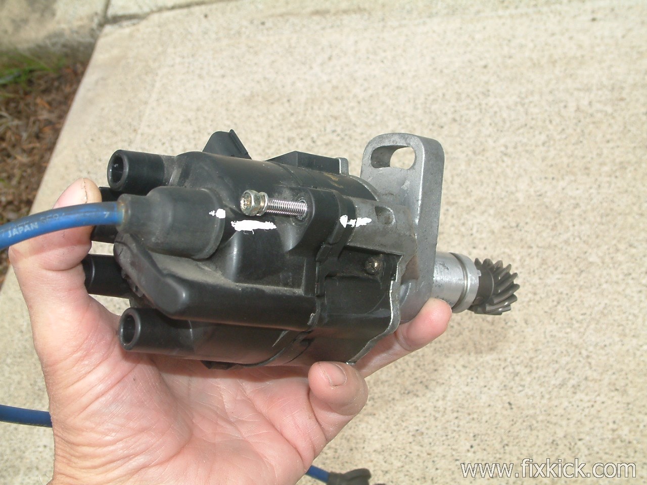
Below is the 1995 G16B distributor, in 1996 the side connector changed a tad and they added a HV igntion coil into the casing. ) (Thanks to Jim L for nice photo)
Best is to put the cap back on, mark #1 , HV tower lug on the base, for more easy alignment.
Don’t forget the timing light works key on cranking, and fuel pump relay removed to cut fuel and set it to 0 degrees firing, as a starting point (if it don’t start first time)
Photo#1
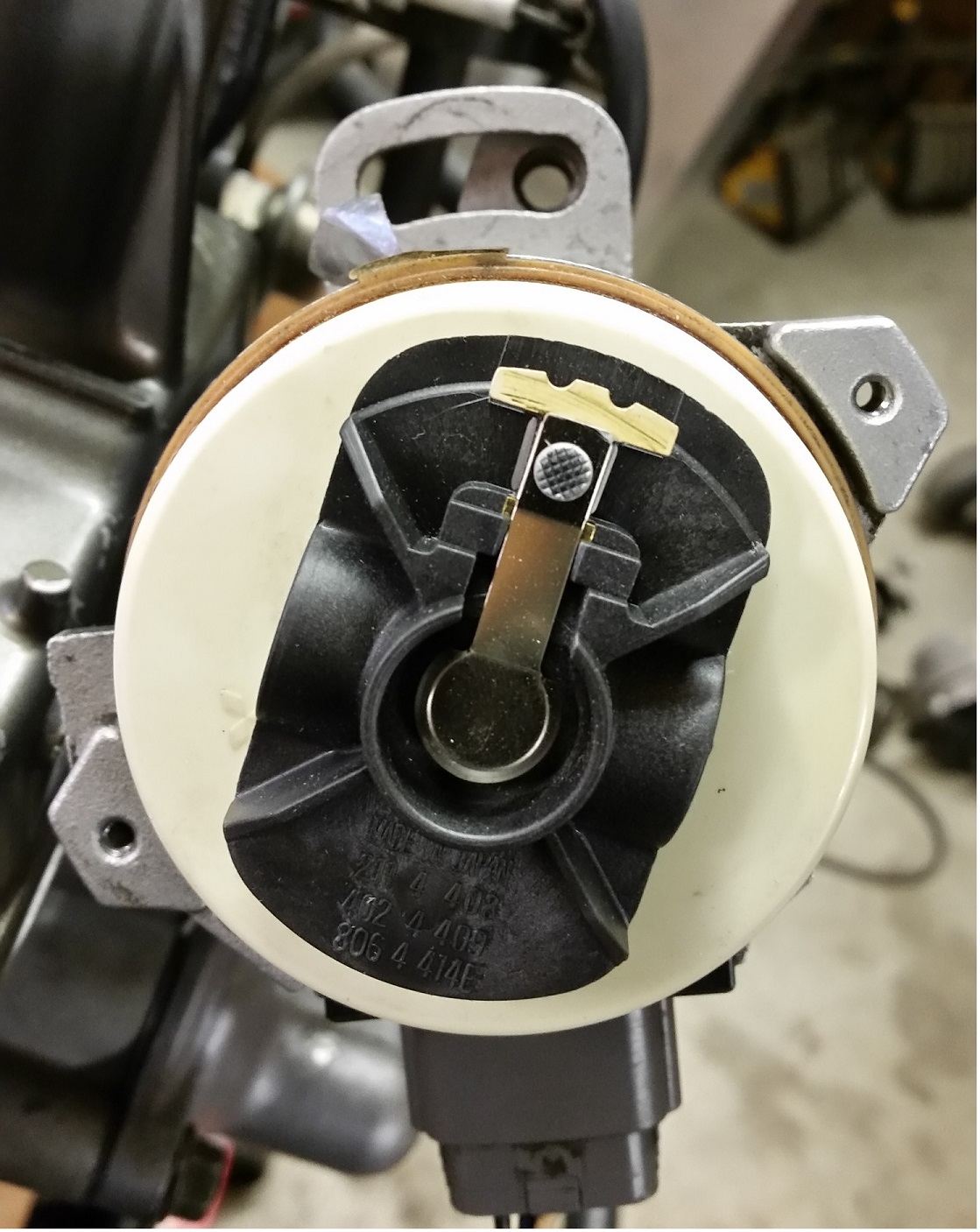
Really nice HR photo , Thanks again JIM!
Again, OEM , 1PM locations TDC #1 firing. FYI :CAM COG, “E” spoke mark is at 6pm , means #1 firing,
This photo below is a crude FSM photo,
The only important issue is marking the base with # 1 location ( Like Here 1, and Here 2 , and last Here 3)
First mark the #1 tower , then the base of tower then the inside of base. I’m using Liquid paper !
Drawing 2, not a GM wrong drawing. The rotor turns CCW. “counter clock wise” ! This real drawing is #1 firing, By Suzuki.

96-98 actual distributor (97 in hand) and my index marks in white.
Note reality is slightly different than the above FSM Go back one page to find the 8v procedure photo. (side connector location , actual)
The base MOUNT is 12 O-clock. that is our reference point.
The below is 1996-98. note the coil HV lug, ! its timed the same way as 92-95 distributors. see my #1 markes in white, I used the cap fitted to find those. The 96 has the side connector moved…
Photo2:
The distributor can be timed to any of the 4 High voltage tower posts and run great. but the firing order is 4,2,1,3 and that confuses the heck out of folks, why do that?
But only the above is the OEM way. The harness binds up, in most the wrong ways, so…
If you want to time it to 11pm, 4pm or 7pm , have at it. But don’t expect help from others. (or later usage of same in any FSM)
I see many timed at 11pm. (due to mechanics that follow the 8v books or non OEM manuals, speculation or worse follow any Auto store Rags (book of lies) book)
THE FINE TIMING SETTING Procedure:
Also Known as Dynamic timing ,using a STROBE light.
The engine now runs , so now we adjust the timing for perfection.
You need an electronic strobe timing light. (beg, buy , barrow or rent one).
Before connecting your timing light: (examine spec. values, there are 2 timing values for different years)
Place the DLC Ignition FREEZE jumper.
If the timing will not freeze the EFI is either IN LIMPHOME mode or the throttle TPS idle switch is stuck open (calibrate it)
The timing must not bounce if it does repair the causation of Limphome or correct the below pre-conditions.
- Run the Engine until fully hot. (180F or more ,and idle at 800 RPM and all accessories OFF)
- Set the Freeze jumper per above. ( if it won’t freeze , stop bouncing then key off and restart jumper in place.)
- This Action tells the ECU to freeze the Ignition timing. “Other wise it bounces like crazy” See comments at the end for Bouncing issues.
- Set the Idle to 800 RPM HOT via the Throttle body Air horn bleed screw, here.
- Connect the timing light and point it at the crank damper pulley and SCALE and the lower front Timing belt cover.
Connect the timing light power wire clips to the battery , red to red ,black to black.
Clamp the Timing light ,inductive clip to #1 spark plug HV cable. (the spark wire, #1 is front).
Using a electronic timing light set your timing by moving the Distributor base just a tad. Set it to the mfg , specifications.
Again, if the timing wiggles by itself , the ECU diagnostic jumper in front of the battery has the jumper set WRONG !!! or other input to ECU is wrong.
- The Distributor has a clamp bolt, loosen it a tad, rotate the Distributor just a little and the timing marks on the Crank pulley will move in relation to the Timing belt cover. there is a tiny scale there. 10||||5||||0 (hard to see black plastic ) ( before TDC, is to the left). See it ? Before Top Dead Center)
- I Paint the timing marks with “Liquid Paper (® )”at two places the Crank notch and the 8 degree hash mark. (or 8degrees. on 96+)
- Move the Distributor until you reach the below timing value and then set the Distributor base clamp tight.
- Your Distributor is now perfectly timed.
- Lock the Distributor clamp down to, about 6 ft/lbs.
- done
Pull the timing freeze jumper and gun the throttle and see a huge advance.
Specification History:
Timing is 8 deg. BTDC ( before top dead center) [ early Kicks ]
In 1996 the Timing dropped to 5 Deg. BTDC, up to year 2000.
RPM is 750- 850 starting in 1996 to 1998
RPM is 700-800 1999 to 2000
BTDC = Before Top Dead Center (firing, NOT exhausting )
The photo below is with the CRANK at TDC 0 degrees and on the Firing stroke and not the Exhaust stroke.
The Freeze Jumper does not work correctly, my timing keeps jumping (bouncing) like crazy. Why?
First thing to know is the bounce is normal on all 1991 to today cars, it bounces for the fact that the ECU moves advance even at idle, and for low smog, low fuel uses and to fine tune idle speeds,.
Normal, so to set timing you need a freeze jumper planted, (Suzuki uses an other name, but freeze is clearer)
Do not panic. The Nine ways to fail freeze, not counting the 1st rule on timing, steps above, all accessories are OFF,
The problem is real and common, the ECU sees a major fault.
The following failures will cause this problem: In ORDER.
- TPS IDLE switch is bad or not closed at idle. (simple TPS calibration is easy) set it for 300 ohms or less. A COMMON FAIL.
- The ENGINE is not HOT, the thermostat is bad 180F is the minimum spec. for temperature of the coolant or Hotter.
- The A/C switch is signaling High Idle falsely. (turn off the A/C or repair the switch as appropriate, the A/C lamp MUST BE OFF)
- You Automatic transmission Park/neutral switch is failure, signaling the ECU pin , I’m IN GEAR , falsely .
- You RPM is not close enough to 800 RPM to make ECU happy ISC failure of ANY KIND ( fact but how far off can cause freeze to fail is unknown).
- ECU is faulting , forcing FAILSAFE MODE or BackUp mode, no idle controls in this mode. (first repair all ECU input devices.) If Diagnotic mode, fails for codes not 12, then BINGO HERE.
- You have Accessories on, turn them ALL off, A/C , Fan, defrost , AUDIO stuff all off. NO ELECTRICAL LOADS , besides Ignition !
- The CEL , Check engine lamp is on DRIVING Repair the car first before trying to fine tune the Ignition timing.
- Power steering overload switch is closed, this causes hot idle to go to 1000 RPM, and fails step 5 above…
Backup mode is when you go to Diag-mode the CEL goes dead or is blank or will never flash anything ever, on demand and is not the silly nag switch set wrong.
Backup mode is DEAD ECU…
Failsafe is usually the ECU sensors inputs dead. not ECU bad. The ECU will show DTCs for gross sensor input errors.
The Marks on all 1.6L motors look like the below. Drawing 3:
One more TDC view: When cranking motor , using the strobe the light falls for each wire connected, (mag pickup) per the below.
If not?, it’s timed all wrong. (proof in pudding)
If the crank key (shears) slips, all marks, on this page are 100% worthless and just whistling in the dark , only a true TDC finder can solve that riddle.
Drawing 4:
Fast Dizzy planting 16v. 1992 to 1998 USA spec. cars.
(firing order is 1,3,4,2 on all 4 cylinder kicks , #1 is front)
There are 4 ways to time the distributor, the below is the FACTORY way. (all 4 ways work, but I’m not covering all ways)
You are here, because all timing was lost, for the Dizzy (Distributor)
Factoid 1: The engine fires every 180 degrees of crank rotation. CW is normal rotation facing rear of car. CW means CLOCK WISE.
This section, is a short version of this: (the below, is short, as is possible)
- Set engine to TDC 0 degrees #1 firing, the valves on #1 (front) cylinder must be loose, that is, lash is loose , if not ? turn the crank 360degrees CW, See mark 2 above, at 0?
- Are you at DTC #1 firing? now? good. if not repeat #1 until it is.
- Drop the dizzy down its hole, with cap off and rotor present (no China clone job rotors allowed, use the real one) and note the rotor location.
- The rotor spins, in your hand, as you do the drop. This is normal for all helix spiral gears, what you do , is anticipate the rate of the rotor movement, and make the rotor land on 1PM.
- See drawings 1 mine, and drawing 2 (factory) this is the correct location. NOW,. lock down the dizzy base screw.
- Next, mark the cap so that #1 is marked on the cap aligned to rotor tip, then lay down high voltage HV spark wires seen in Drawing #1 (in the CCW direction)
- The engine ,will now start and run , last step is timing with a strobe light.
Factoid 2: If in number one, you don’t want to remove the valve cover to watch the valve action , you can remove spark plug #1 and blow into #1 and if can’t blow, it’s firing on #1 (the blow test )
Yes, use a CLEAN hose and lips to do that.
The Gorky way (engine more taken apart)
“if the cam cover is off, put the cam E spoke, mark down, at 6pm and crank mark at TDC 0 mark. This is #1 firing now.
E mark up is #4 firing not #1
Assumptions: (PO = Previous Owners) PIT FALL HELL:
- Cam is timed correctly, if not, this whole page is useless.
- The Dizzy gear is not put on upside down or 180 degrees off. (PO hacking?)
- Someone (PO) installed the Dizzy wrong. Or inanely put it in wrong to compensate for cam timing way the hell off. ( common error)
- The CAM gear rear is not indexed wrong, some are press on gears there an index mark here. (PO hacking?)
- Someone put a POS China knock off Rotor on the Dizzy and it fits on 3 ways, SORRY that is NOT STOCK, no stock rotor does that, FACT ! BOSCH FITS, for SURE.
- The HV wires are not laid down backwards, reading the GM (Geo) & all autostore sold auto repair books., all get this wrong. for 22 years to date . (Suzuki real books are all correct)
- Valve lash set wrong (tight) makes it hard to prove TDC #1 firing, if using this method for TDC #1 firing. (lash loose on #1? checked?) < done at engine build time.
- The infamous, crank cog key way, is not sheared.
- You used the freeze jumper, per the book and it fails? Why?
- The spark is blue/white hot and great, out of the Ignition (induction)Secondary Coil. output “the Mr. Tesla magic” Test spark at the coil before condemning any spark parts , first.
- Cap and rotor not carbon tracked. (tune up time at 60k)
- HV spark wires dead, open or insulation long ago, failed, No spark plug wires on any engine last the life of ANY engine. period. It’s called a tuneup.
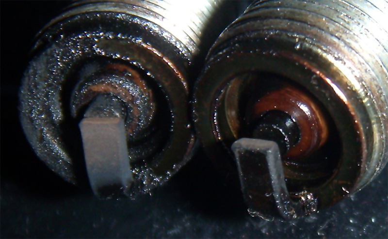
- Spark plugs fresh, not black as an ace of spades.
- If the Dizzy is timed way off, or rotor is from China, (knock off crap) the spark happens in the middle of cylinders or not at all, and the timing light will be dead or act real odd.
- Cam gear using wrong key way slot, someone used “I” and not the proper “E” slot.
- The Previous owner used the “I ” timing slash marks to time the cam, this is totally wrong it must be the “E” timing mark on the cam cog. Never use “I” anything or FAIL HARD.
- The PO thinks that the cam is timed at #1 cylinder, but it is not, it is only timed (timing belt) at #4 firing. Sorry, but those are the facts, no matter how many freakn Toyota’s you’ve timed.
I’m sure I missed , something…
RELATED:
O-Ring data: see dizzy Oring sources and part numbers here.
this is my old page from 2007,
the 96 + distributor has internal spark coil now and side harness connector a bit different
and the 96+ distrib does not run on a pre 96 ECU. OBD1 and OBD2 distribs are not the same.
nor 92-95 run on 96+ car, same reasons.
but do time the same way and never like any 8valve engine.
Good job guy’s