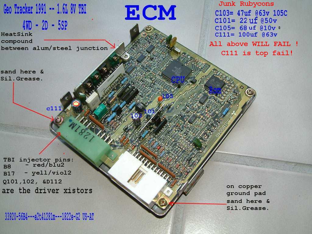
(8 valve TBI EFI ECU) Reverse engineering data:

ECU Suzuki P/N: 33920-56B40 : made by Mitsubishi. or B30
Throttle body single Injector (TBI) Sidekicks /Trackers, only, up to 1995.
My parts substitution page.
See this 8v ECU:
See my transistor test methods , here. (more links and examples)
The 8V ECU, used in USA. "disected by me"
The major output transistors: ( if this function fails , replace the related transistor)
Never short any of these PINs to 12vdc battery feed of any kind. Death of ECU.
A shorted Injector will blow up the ECU driver and no CEL code will happen.
| PCB ID |
PN: |
FUNCTION |
B=green A=white Conn. |
| Q100 |
2SB1018 |
ISC Idle sol. |
PIN B6 |
| Q101 |
2SB1020 |
INJECTOR + |
PIN B8 |
| Q102 |
2SD1415 |
INJECTOR - |
PIN B17 |
| D112 |
Emu-m11 |
diode flyback |
PIN B8 |
| Q103 |
2SC2562 |
ISC -Idle sol. |
PIN B6 |
| Q104 |
E1F3P |
TCC RELAY |
PIN A11 torque
converter |
| Q106 |
E1F3P |
NC on TB |
PIN B4 |
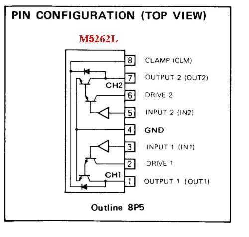
| IC11 |
M5262L |
FUEL PUMP RLY |
Pin B16 |
| DIODE |
TO GROUND |
MAIN RELAY |
Pin B15 |
| IC11 |
M5262L |
Fast idle VSV | Pin B14 |
| IC13 |
M5262L |
EVAP VSV |
PIN A8 |
| IC12 |
M5269l |
EGR VSV |
PIN B5 |
| IC12 |
M5262L | THROTTLE VSV |
PIN B14 |
| IC12 |
M5262l |
CEL MAP DRIVE |
PIN B13 +10 OHM Resi. |
| IC14 |
M5262L+D20 |
Igniter driver |
A12
Igniiton driver. |
| IC10 |
custom device |
5 vdc power supply |
Pin 14 on device |
| D107 |
16V zener diode IN4745 |
Pin A23 protection |
stops all plus/minus spikes protects IC10 ! |
If any of the loads connected to any of the above pins, shorts to veh. +12vdc, the result will be a burned out transistor or IC.
This can occur with a shorted coil in a VSV or by someone who likes to HOTWIRE things , which is never done with electronics, unless you have full information on what you are doing and what will happen. (a rare event on Car OEM parts).
M5262L is serious UNOBTAINIUM http://en.wikipedia.org/wiki/Unobtanium/
How ever I can substute transistors. for M526x , here is my theory on this practice.
ask for help here.
As for IC 10. ( a custom Mitsubish hybrid chip device, on custom ceramic substate, only way to get one is by cannibalization of worse ECUs )
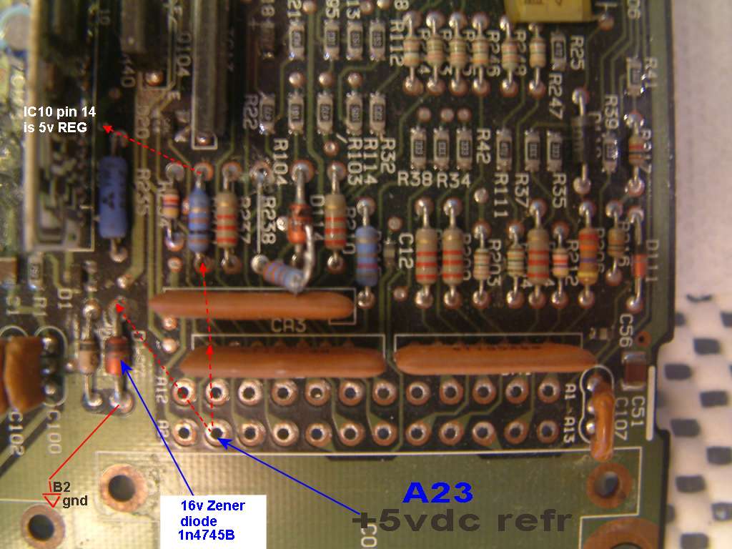
| Common problems: Crappy BLACK RUBY CAPS syndrome: (seen 100's now) C111, LIKES TO BLOW TO PIECES and leak acid, 100uF at 50v, 105 deg. C. Change all Aluminum top Capacitors ! The Rubycon's are trash !(circa 89-95) Silver alumin top CAP's, are electrolytic, if new already , skip this. Cleaned with Bicarb Soda, and flushed and scrubbed with Alcohol. Newer CAPs will be non Black, and will have a imbossed cross on the top.! This cross is new fangled , explosion protecting ( yes they can rupture violently) Look for smoke or acid spills in case. Pin A23is dead syndrome: +5v refr pin output to sensors. +5V Vref traces like to blow up, Vaporize ! Place jumper at R205 to Pin A23 if that happens.SEE DRAWING HERE. Cause 1, by sacrificial zener diode D107 , that guards the 5vdc Vref pin, SHORTING. D107 is a 16v Zener Diode, reads 16.6v actual on my Tek curve tracer ! 1N4745B (B is most accurate, A suffix or blank are way less and are OK) Cause 2 (5v dead) , someone hot wired pin A23. +5vdc is uses all over the board for LOGIC, even the processor. Make sure IC10 pin 14 is at 5vdc or its then end of the road for ECU and IC10 MAIN POWER LOST on left rear of PCB: The plated thru hole under c111 was vaporized , leaving no power to whole board. (oops) The C111 + pad is a plated through hole and if missing the ECU will be DEAD. Acid can cause this. (leak) I had to jump this Power path too. Do not drill this 3 layer board! I finished the above and plugged it in to my Kick and it runs perfect and enters closed loop. I now have a spare ECU. Happy feet ! There are many other failure points, all are random and impossible to list. but the above are so common, it's a crime. |
All the parts marked with Mxxxxx are Mitsubishi parts.
The M52xxL parts are impossible to get. So pray they don't pop. (how ever they CAN be substituted , easily , ask me )
All the descrete parts can be subsituted , very easily.
( I can measure the beta of any transitor and the buy one just like these, they are only switches.)
Here the schematic of the 5262:
M5269L is here.
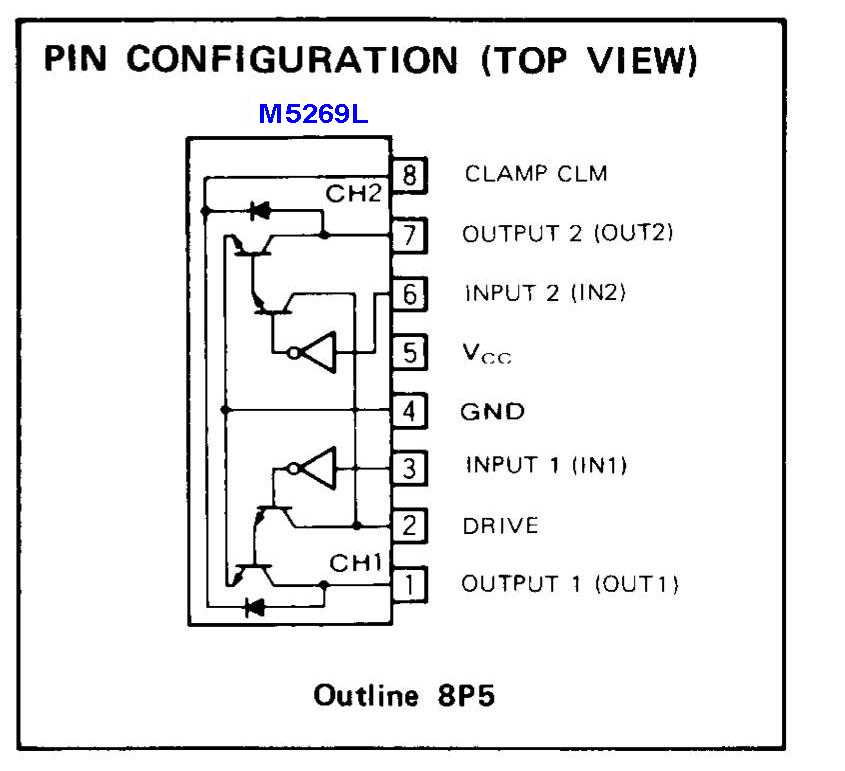
See Substitutes at the end of this document.
The 2SA,2SB,2SC and 2SDxxxx parts are all available from MCM electronics .
My bench test (crude):
Below, I made (no where else on earth) a schematic of the Injector driver.
If you don't have injection, replace q101 and 102 and the .27 resisior if open.
As you can clearly see the Injector is never ground full time, NOR IS IT HOT FULL TIME LIKE MPI 16V!!!
To zoom or print , please click the drawing below, to expand it.
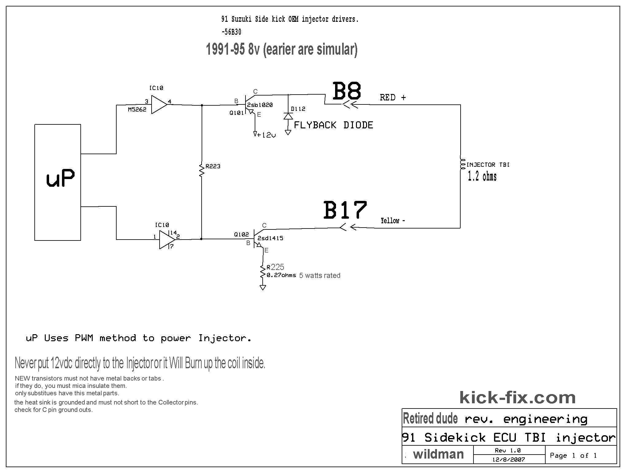
Click to zoom or print above IMAGE.
Both Injector driver transisors are high gain Darlingtion type (twin cascaded).
Some say these old ECU's are weak, but consder this? they can be repaired , unlike lots of new ones. ( like the plastic potted ECU , repair that !)
To my knowledge, the only weakness is the Electrolytic cap.' s that love to leak and are marked RUBYCON.
BIPOLAR Transistor test: PHASE 1, basic multimeter tests.
Be careful some Automotive tranistors (drivers) they have clamp diodes built in and will conduct with the minus meter to Collector and red test lead on Emitter pin.
Always test a 1N400x (or simular) Diode first , because some crazy meters use MINUS battery on the red test lead (yes crazy ,and common on old analog meters)
This diode test proves the meter is working as expected. !
Examples of Phase 1
Here Here and here with a cute solar cell IDEA !.
YES, YOUTUBE.
This transistor are bipolar type (non FET & non MOSFET) devices and can be tested with 5 checks of an Ohm meter.
NPN is very common on ECU's !
The modern meter MUST have a diode position on the Resistance scale. If it does not, it can not measure a diode. (mostly) (or use an old analog meter)
Do not use any old Simpson 260/270 meter with that huge 22vdc battery , DO NOT. It can kill some transistors. Open bottom, see battery.
Use modern meters , modern meters use about 0.25volts on Ohms and then use 2 volts on Diode mode.
0.25v will not forward bias any silicon junstion , not even Schottky junctions.
The below shows a diode form that acts like a transistor. ( but has no gain or transfer functions) This Graphic allows you to check for continuity and shorts and opens.
If your meter (mine does) shows the barrier voltage during diode test ?, you can find damaged junctions? ( not .7v (one junction) or 1.4v for darlingtons)
A junction with below 0.4v is damaged.
So be sure you know how your meter conducts, DIODE check? ( ohms or barrier voltage style)?
 Q102 looks like this to a meter, like 2 diodes.
Put the red meter lead on the Base, the black on the Emitter pin. It must show 1 to 10 ohms. (or .7v) or 1.4v for darlingtons.
Please be aware the some fancier meters, actually measure the barrier voltage. So 700mv is conducting. Infinity (or max V) is open.
Practice for 5 minutes with a simple diode to become familiar with your meter. <<< very important to do 1 time ! and read its manual !
Make sure B to E junction conducts Red on B , Black lead on E, then reverse the leads Black on Base, it must then not conduct.
Next, is Place Red on B and black lead on C. It must again conduct, and when the leads are reversed, it must not conduct.
Last make sure C to E , both way reads infinity. (cept on transistors with clamp diodes , common on ECU's) Black test lead on C might conduct (but rev, it must not)
Q101 above grapic, is tested exactly the same, but the diodes are backwards from above. so all the tests are reversed.
exchange all mentioning of RED to Black above.
EG: black on Base , Red on E , must conduct.
The transistor must be removed to test it. Look for cracks or any signs of overheating , bulges or discoloration, of parts or traces
If transistor looks bad, it is, the traces can always be repaired.
If your DMM has a transistor beta tester in it ,then follow the instructions with the meter to test it. PHASE 3.
Just plug it and and rotate knob to NPN (q102) and the beta (gain) will be shown on the meter. ( this is the amplification factor, beta).
This test is of course far superior to my junction test above.
The 16 valve car uses a single type transistor to drive each of the 4 injectors using a Ground sinking transistor simular to Q102 and all 4 injectors tie directly to the 12vdc Ignition power source. Go back one page to see Transistor ID's and part numbers for the 16v ECU, it is well documented by me.
IC Above, means Datasheet stated continious collector current, or Maximum IC, max IC .
Phase 2 , Measure the GAIN of the transistor. Beta or HFE, many DMM come with this test port.
BETA ir hFE or Bf , Beta is DC current gain , amplication , or as scientist, call this the tranfer function.

Beta's very from 10 to 2000 on ECU transistors. 100 is very common value.
Our injector drivers are super Beta , aka: Darlington transitors hFE = 2000 are common.
hFE equations
Tools , meters and testers:
The Beta tester kit.See DT100 kit. $30
Here is a cheap meter at Amazon for under $20 with a built in Beta test function. By Elenco. M1007K
$10 here or go whole hog.
Run wires to socket and to large transitors, to test.
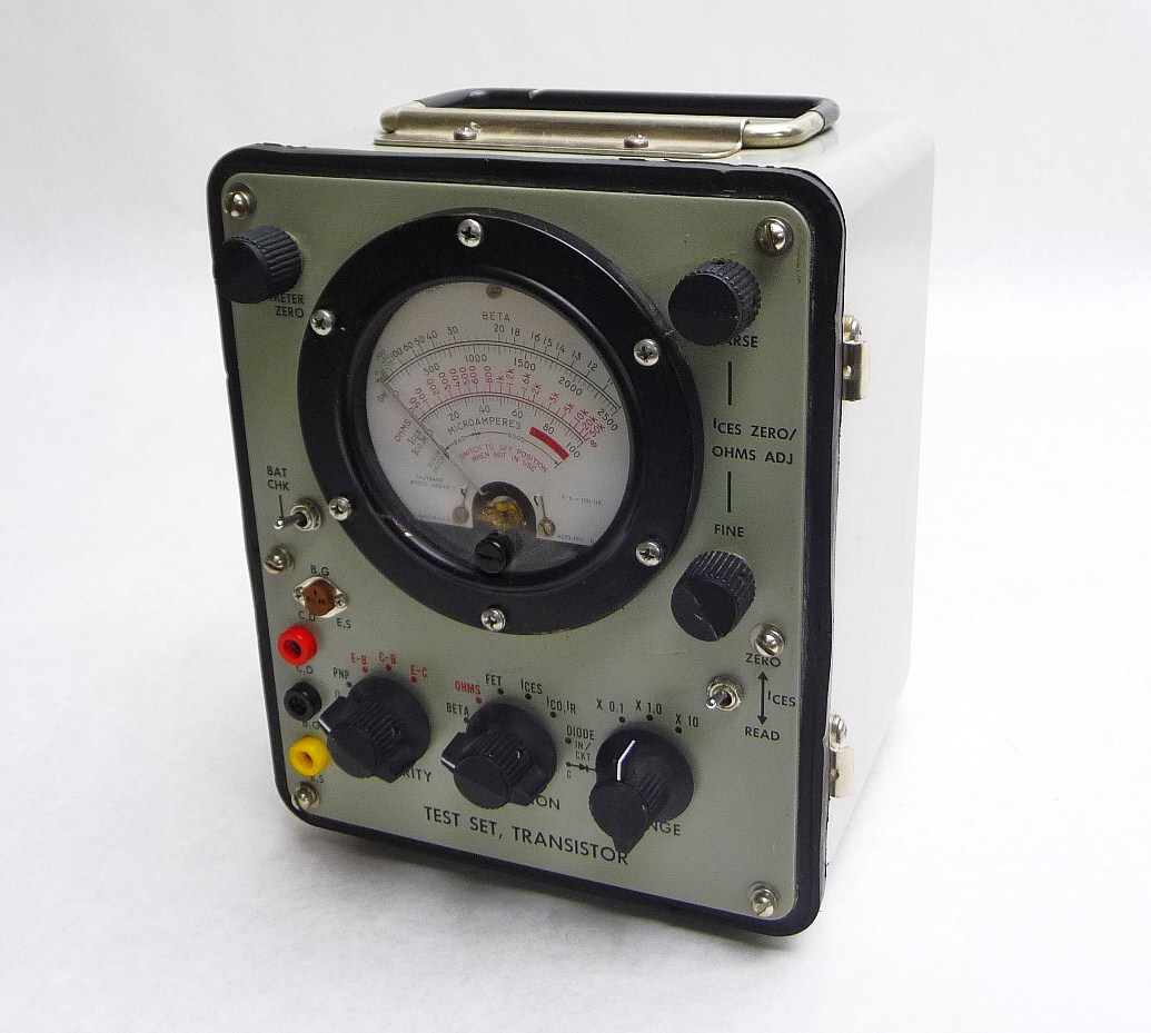
The below and is Old, but very nice HICKOK. ( The company was famous for Electron Tube testers in the USA)
TS-1836D/U
Now collectible. This classic meter. (just joking, I do collect old meters) I used to test and repair all instruments in the USN.