| Factory
spec. |
Spec
Ohms |
Data measured in
Fahrenheit Ohms |
medium | Calc. | ||||
| Temp.
C° (F) |
Coolant ECT |
AIR
IAT |
ECT mine ohms |
ECT Temp. F |
IAT mine ohms |
IAT Temp. F |
tested | Volts ECT |
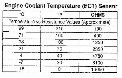
| -18(0) |
14650 |
4.4v |
||||||
| -7 (20) |
8100 |
4.0 |
||||||
| 0
(32) |
5800 |
6100 |
5600 |
33 |
5600 |
33 |
H²O | 3.7 |
| 4 (40) |
4780 |
3.5 |
||||||
| 20
(68) room |
2450 |
2600 |
2450 |
69 |
2550 |
71 |
air | 2.8 |
| 21(70) |
2350 |
2.7 |
||||||
| 38(100) |
1250 |
1724 |
81 |
1900 |
81 |
H²O | 1.9 |
|
| 40
(104) |
1400 |
1200 |
5030 |
36 |
5200 |
42 |
air | 2.1 |
| 60
(140) |
580 |
620 |
-- |
-- |
-- |
-- |
-- | 1.1 |
| 71(160) |
400 |
.83 |
||||||
| 80
(176) |
320 |
340 |
-- |
-- |
-- |
-- |
-- | .69 |
| 82(180) |
300? |
300? |
.65 |
|||||
| 99(210) |
190 |
.43 |
||||||
| pan boiling water |
unk |
unk |
205 |
212 |
210 |
212 |
H²O | .46 ? |
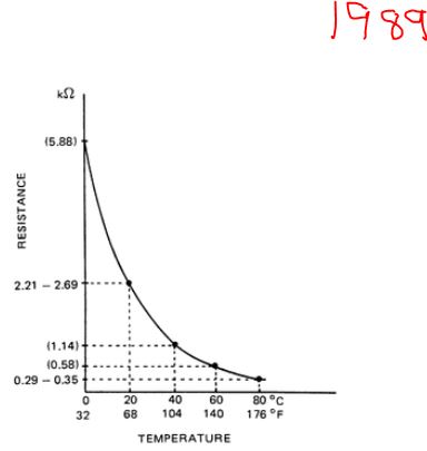
| FSM GM & Suzuki | FSM |
FSM |
new |
new |
? estimate |
|||